Multiple access communication system and data transceiver

a communication system and multi-access technology, applied in the field of multi-access communication system and data transceiver, can solve the problems of increasing the length of time that other slave stations must wait until transmitting transmission data, reducing the utilization rate of multiple access lines, and increasing the delay in transmission data, which is required in real time, to achieve high utilization rate

Inactive Publication Date: 2006-10-19
NEC CORP
View PDF4 Cites 3 Cited by
  • Summary
  • Abstract
  • Description
  • Claims
  • Application Information

AI Technical Summary

Benefits of technology

[0012] The present invention has been conceived in view of the above described situation, and a first object of the present invention is to provide a multiple access communication system and a data transceiver allowing always highly efficient utilization rates for multiple access lines.
[0013] A second object of the present invention is to provide a multiple access communication system and a data transceiver avoiding an uplink to be occupied by a single slave station for a long period of time.
[0014] A third object of the present invention is to provide a multiple access communication system and a data transceiver allowing reduced delay of transmission data that is required in real time.
[0016] A fifth object of the present invention is to provide a multiple access communication system and a data transceiver allowing uplink control information to be transmitted with priority over uplink user data.

Problems solved by technology

By doing this, if the size of the additional information becomes large compared to the size of the transmission data, the concatenating of a plurality of transmission data for transmission suffers from a first problem that conversely the utilization rate of the multiple access lines is degraded.
Also, when a slave station concatenates and transmits a plurality of transmission data, the uplink is occupied for a long period of time so there is a second problem that the length of time that other slave stations must wait until transmitting transmission data is increased.
Accordingly, there is developed a third problem that a delay in transmission data, which is required in real time, is increased.
Since transmit packets in a transmission buffer are transmitted automatically one by one, in order to concatenate and transmit transmission data there is a fourth problem that it is necessary to have completed concatenating processing by the time transmission data is put into the transmission buffer.
Accordingly, there is a fifth problem that the uplink control information is not given priority over the uplink user data when performing transmission.

Method used


Image

  • Multiple access communication system and data transceiver
  • Multiple access communication system and data transceiver
  • Multiple access communication system and data transceiver

Examples


first embodiment

[0051] A first embodiment of the present invention will be described in the following, with reference to the drawings.

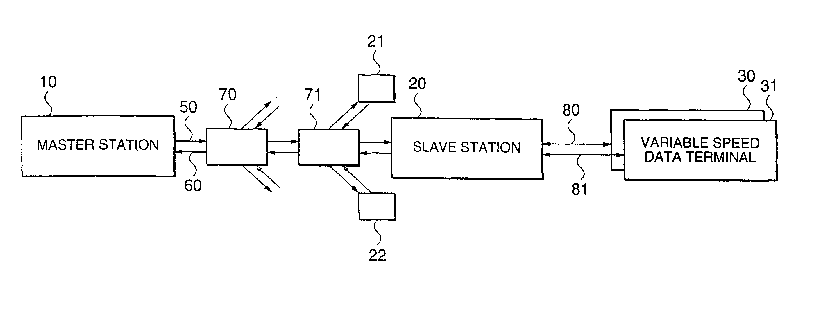
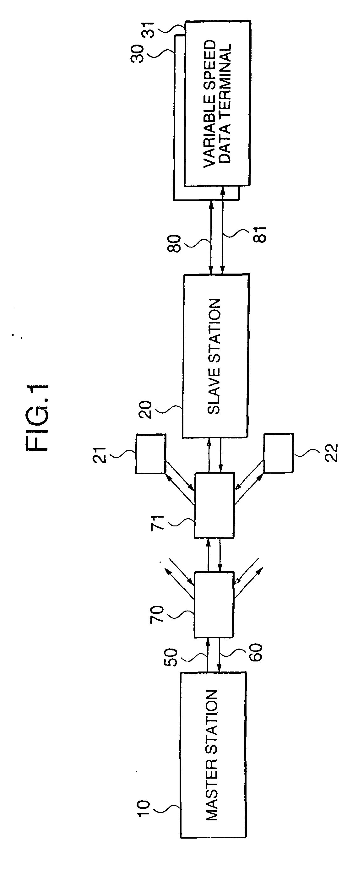
[0052]FIG. 1 is a block diagram showing a multiple access communication system of this embodiment. In this drawing, a plurality of slave stations 20, 21 and 23 receive data and control information from a master station 10 through a broadcast line 50. The master station 10 receives data packets and control information packets from the plurality of slave stations through a multiple access line 60. Also, the slave station 20 is connected to a variable speed data terminals 30 and 31 through variable speed communication lines 80 and 81 respectively.

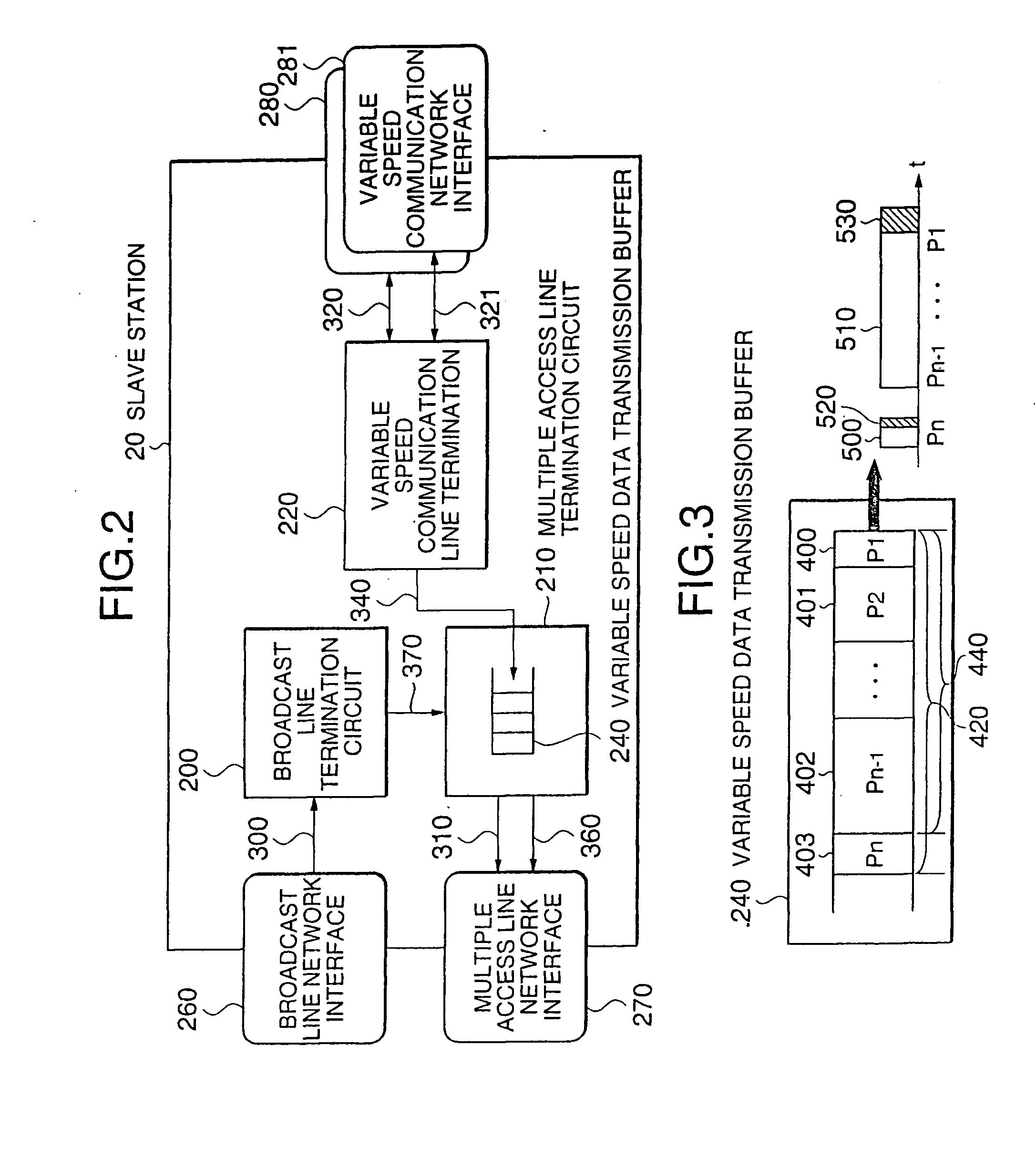
[0053]FIG. 2 is a block diagram showing the above-described slave station in detail. A broadcast line termination circuit 200 receives data from the master station, while a multiple access line termination circuit 210 transmits data to the master station. A variable speed communication line termination circuit 220 transmits a...

second embodiment

[0057] Next, a second embodiment of the present invention will be described with reference to FIG. 1, FIG. 2 and FIG. 4.

[0058]FIG. 4 is an example of the format of an uplink transmission data packet according to the second embodiment. When uplink transmission data packets P1, P2, . . . Pn-1, Pn are held in the variable speed data transmission buffer 240, the multiple access line termination circuit 210 reads out an internally held transmission condition. When an upper limit value for a concatenated data packet size has been set in the transmission condition, the multiple access line termination circuit 210 performs concatenating for only a concatenated data packet size 430 that does not exceed the upper limit value, adds a concatenated transmission overhead 530 to the concatenated transmission data packet 510 and transmits a resultant packet to the master station 10 through the multiple access line network 60.

[0059] For example, assuming that the upper limit to the concatenated da...

third embodiment

[0060] Next, a third embodiment of the present invention will be described with reference to FIG. 1, FIG. 2 and FIG. 5.

[0061]FIG. 5 is an example of the format of an uplink transmission data packet of this third embodiment. When uplink transmission data packets 400, 401, 402 and 403 shown as P1, P2, . . . Pn-1, Pn are held in the variable speed data transmission buffer 240, the multiple access line termination circuit 210 reads out a transmission condition for packet concatenation. Processing is set for the case where a concatenated transmission overhead size meeting the transmission condition is smaller than the total size of individual transmission overheads.

[0062] In the case of individual transmission, transmission overheads 520, 521, 522 and 523 shown as H1, H2 . . . Hn are individually added to uplink transmission data packets 400, 401, 402 and 403 and are transmitted. Also, in the case of concatenated transmission, the uplink transmission data packets 400, 401, 402 and 403 ...


PUM


Abstract

A multiple access communications system achieving an improvement in transmission efficiency is disclosed. A slave station receives data from variable speed data terminals and generates a plurality of data packets. The slave station then transmits a transmission request packet containing a total amount of data packets to be concatenated to a master station. The master station transmits a transmission permission packet containing a total amount of data packets permitted to be concatenated through a broadcast line to the slave station. The slave station concatenates a plurality of uplink transmission data packets within a predetermined range, and transmits a concatenated uplink transmission data packet to the master station through the multiple access line network.

Description

BACKGROUND OF THE INVENTION [0001] 1. Technical Field [0002] The present invention relates to a multiple access communication system and a data transceiver used in a broadband access network or the like. [0003] 2. Related Art [0004] Broadband access networks such as cable modems using cable television lines or Fixed Wireless Access (FWA) using fixed radio channels have been provided even in ordinary households to implement high speed internet access. Cable modems and FWA are described in detail in, for example, Nikkei Communication, No. 316, April 2000. These broadband access networks nearly all use multiple access lines where a number of users share the same frequency band as an uplink, in order to reduce costs. With multiple access type lines, each slave station is connected to a master station through shared media for sharing the same frequency band with other slave stations, and a transmission order between slave stations is controlled by master station multiple access control. ...

Claims


Application Information

Patent Timeline
Patent Type & Authority Applications(United States)
IPC IPC(8): H04B7/212H04B7/26H04L12/44
CPCH04B7/2612H04W74/00H04W56/00H04W28/06
Inventor SUDA, YUKINORI
Owner NEC CORP
Why Eureka
Try Eureka