Functional porous ceramic preparation device and method

A technology for porous ceramics and preparation devices, applied in the field of porous ceramics, can solve the problems of dust pollution in the working environment, large engraving error rate, and low engraving efficiency, and achieve the effects of reducing labor intensity, fast processing speed, and increasing practicability

Inactive Publication Date: 2021-04-23
袁强
View PDF9 Cites 1 Cited by
  • Summary
  • Abstract
  • Description
  • Claims
  • Application Information

AI Technical Summary

Problems solved by technology

[0003] The invention patent of the patent application publication number CN105619577A discloses a special engraving equipment for fully automatic ceramic surface processing. Compared with the prior art, it drives the manipulator through the up and down movement of the No. 1 hydraulic cylinder and the circular transmission mode of the four transmission branches. The fully automatic engraving operation on the outer wall of the ceramic body solves the problems of long processing time, high labor intensity, high engraving error rate, and low engraving efficiency in the existing manual engraving processing methods, and also realizes fully automatic engraving on the ceramic surface. Engraving function, and has the advantages of short processing time, high engraving precision, no need for manual processing and high engraving efficiency. However, in the actual use process, the friction between the engraving knife and the ceramic body will generate a lot of dust. This technical solution does not control the dust. Processing will cause dust to pollute the working environment, and manual secondary cleaning is required in the later stage. At the same time, it can be further optimized in terms of improving processing efficiency.

Method used


Image

  • Functional porous ceramic preparation device and method
  • Functional porous ceramic preparation device and method
  • Functional porous ceramic preparation device and method

Examples


Embodiment Construction

[0032] The following will clearly and completely describe the technical solutions in the embodiments of the present invention with reference to the accompanying drawings in the embodiments of the present invention. Obviously, the described embodiments are only some, not all, embodiments of the present invention. Based on the embodiments of the present invention, all other embodiments obtained by persons of ordinary skill in the art without making creative efforts belong to the protection scope of the present invention.

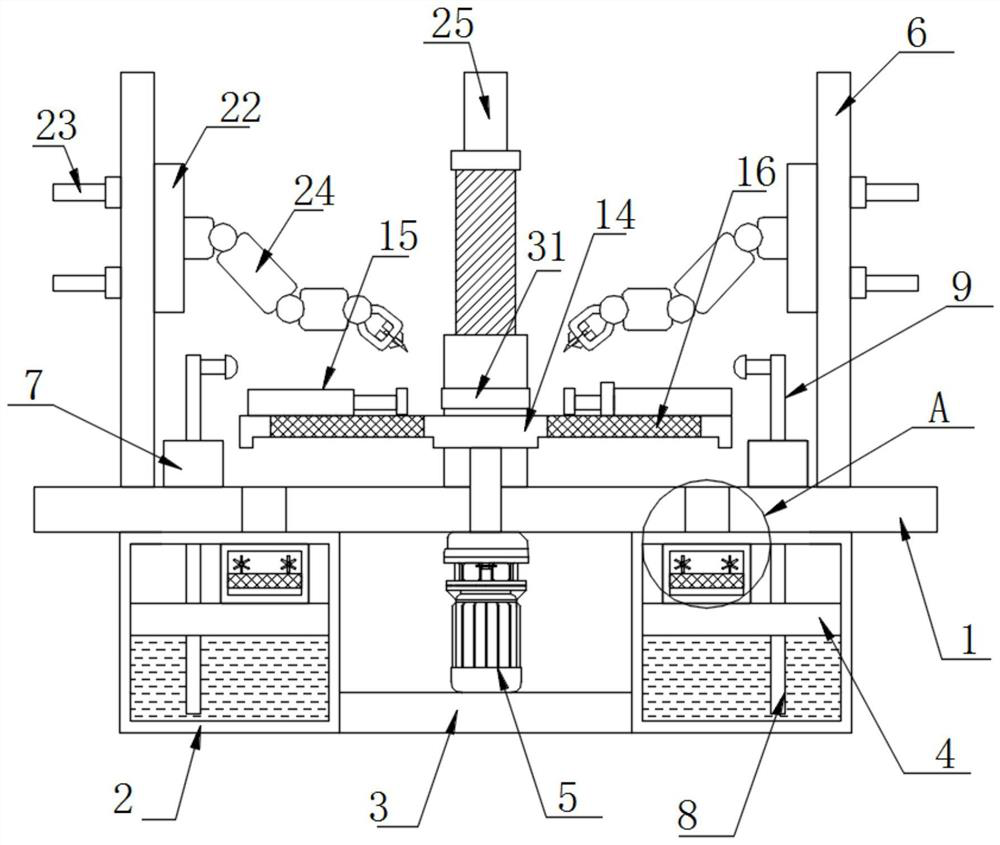
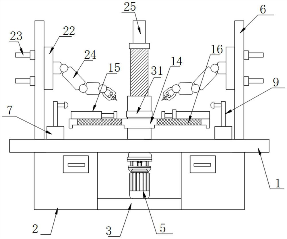
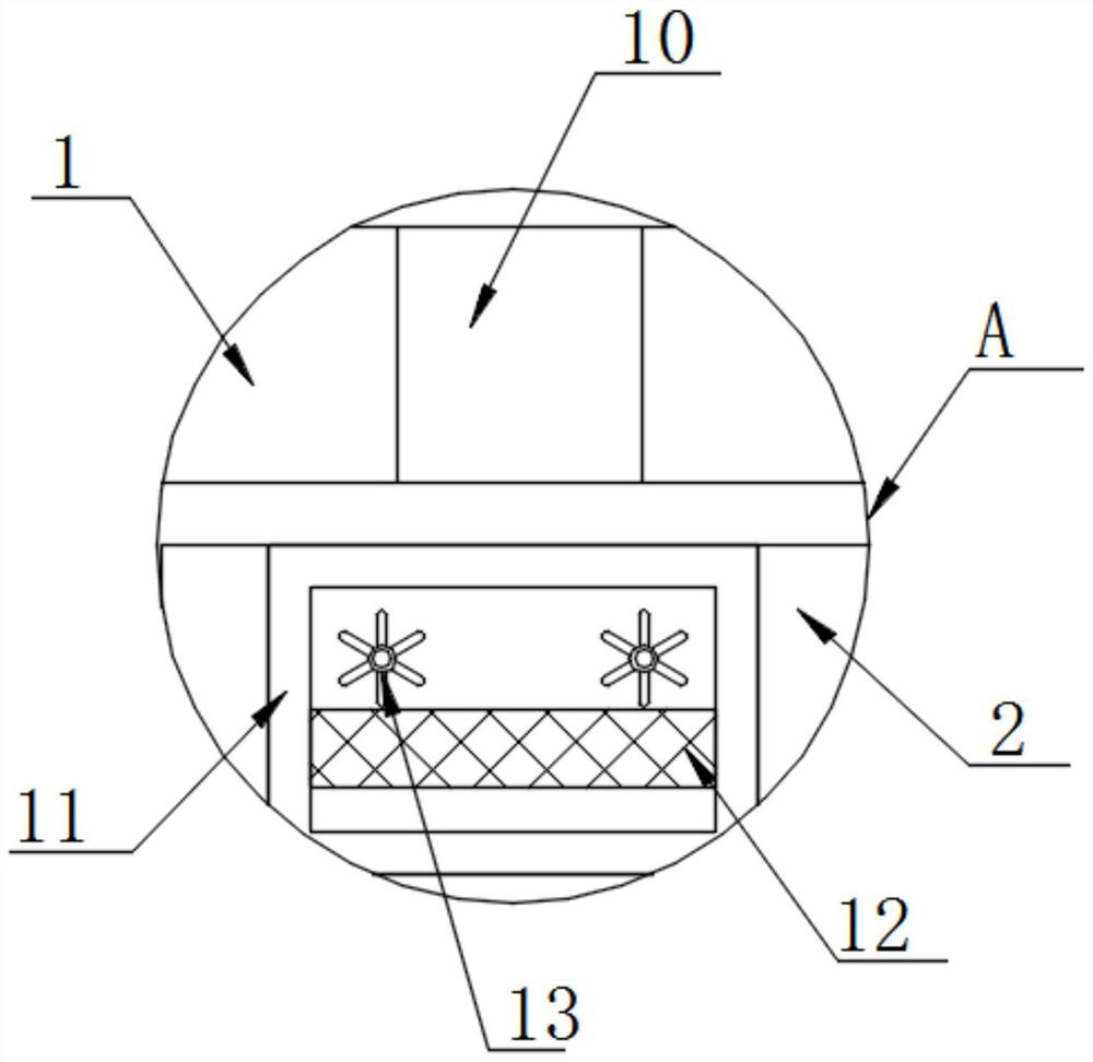
[0033] as attached Figure 1-4 A preparation device for functional porous ceramics shown includes a partition 1, bottom boxes 2 are fixedly installed at the left and right ends of the bottom surface of the partition 1, and the sides between the two bottom boxes 2 are fixedly installed. There is a base 3, a motor 5 is fixedly installed on the top of the base 3, a water diversion plate 4 is fixedly installed in the middle of the inner cavity of the bottom box 2,...


PUM


Abstract

The invention discloses a functional porous ceramic preparation device, and particularly relates to the field of porous ceramics. The functional porous ceramic preparation device comprises a partition plate, bottom boxes are fixedly mounted at the left and right ends of the bottom surface of the partition plate, bases are fixedly mounted on the side surfaces between the two bottom boxes, and motors are fixedly mounted at the tops of the bases. Water distribution plates are fixedly installed in the middles of inner cavities of the bottom boxes, a top box is fixedly installed at the top of the partition plate, and water pumps are fixedly installed on the left side and the right side of the bottom face of an inner cavity of the top box. The water pumps and water spraying pipes are arranged to conduct water washing on the machining position, so that dust and water are fused and discharged, the stability of the machining process is guaranteed, the labor intensity of operators is effectively reduced, meanwhile, multiple mechanical arms can be used for machining the surface of a ceramic blank at the same time, and compared with the prior art, the machining speed is higher, the machining efficiency is higher, and the functional porous ceramic preparation device is suitable for industrial ceramic production.

Description

technical field [0001] The invention relates to the technical field of porous ceramics, more specifically, the invention relates to a preparation device and a preparation method of functional porous ceramics. Background technique [0002] The porous ceramic material is a kind of porous ceramic material with open pore size and high open porosity, which is made of corundum sand, silicon carbide, cordierite and other high-quality raw materials as the main material, and is prepared by molding and special high-temperature sintering process. High temperature, high pressure, acid, alkali and organic medium corrosion resistance, good biological inertness, controllable pore structure and high opening porosity, long service life, good product regeneration performance and other advantages. [0003] The invention patent of the patent application publication number CN105619577A discloses a special engraving equipment for fully automatic ceramic surface processing. Compared with the prior...

Claims


Application Information

Patent Timeline
Patent Type & Authority Applications(China)
IPC IPC(8): B28B11/00B28B17/02B25J11/00B01D29/56
CPCB01D29/56B25J11/0055B28B11/001B28B17/02
Inventor 袁强
Owner 袁强
Why Eureka
Try Eureka