Frequency synchronization apparatus and frequency synchronization method

a frequency synchronization and frequency synchronization technology, applied in the direction of synchronization signal speed/phase control, digital transmission, electrical apparatus, etc., can solve the problem that the reception apparatus cannot obtain the original transmission data correctly, the absolute phase of the reception signal cannot be corrected, and the bit error rate increases

Inactive Publication Date: 2006-10-19
PANASONIC CORP
View PDF8 Cites 30 Cited by
  • Summary
  • Abstract
  • Description
  • Claims
  • Application Information

AI Technical Summary

Benefits of technology

[0013] In order to solve the stated problems, the object of the present invention is to provide a frequency synchronization apparatus and a frequency synchronization method that can be applie

Problems solved by technology

This is because the reception apparatus will be unable to obtain the original transmission data correctly if it demodulates the reception signal without having established synchronization.
However, although they correct the frequency error of the reception signal, the conventional apparatus and method do not correct the absolute phase of the reception signal.
This gives rise to a problem of an undesirable result being obtained by an apparatus at a latter stage when the latter-stage apparatus uses absolute phase as a reference to process the signal obtained by the conventional apparatus and method.
For example, if the latter-stage apparatus is a demodulator that demodulates the signal with-reference to absolute phase, an increased BER (bit error rate) occurs because the demodu

Method used


Image

  • Frequency synchronization apparatus and frequency synchronization method
  • Frequency synchronization apparatus and frequency synchronization method
  • Frequency synchronization apparatus and frequency synchronization method

Examples


first embodiment

[0062] The following describes a frequency synchronization apparatus of a first embodiment with reference to the drawings.

[0063]

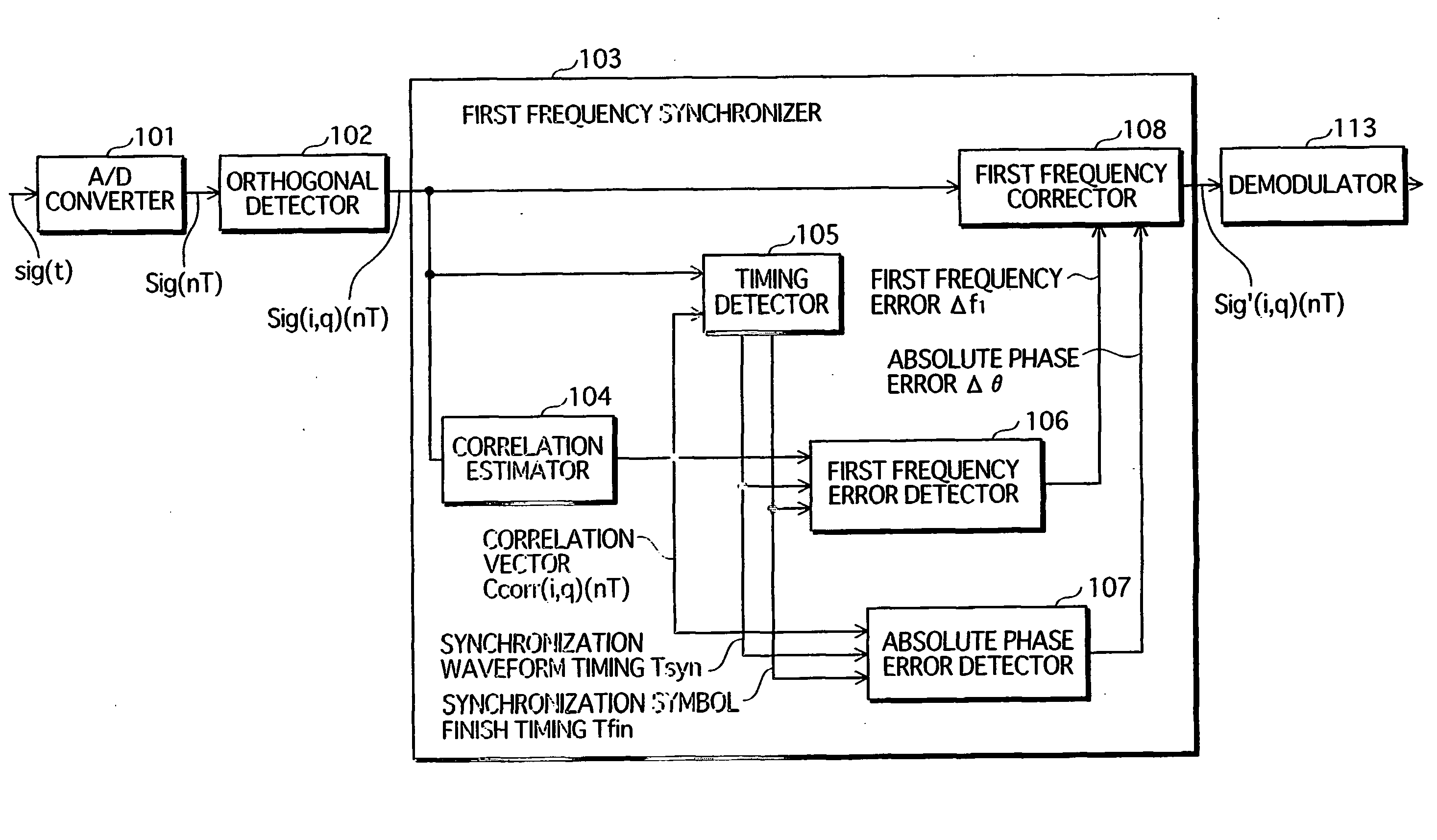
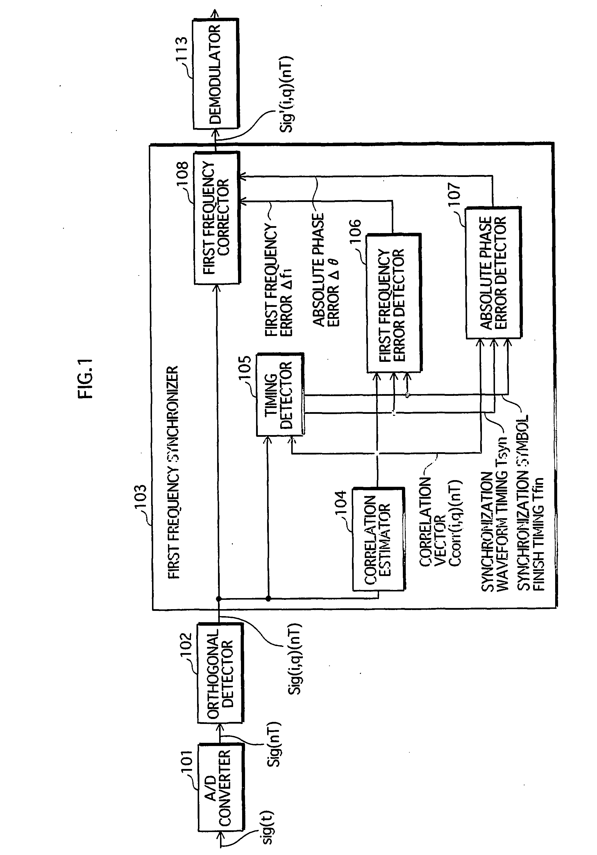
[0064]FIG. 1 is a functional block diagram showing the overall structure of the frequency synchronization apparatus of the first embodiment, together with part of the wireless reception apparatus that is the higher apparatus. In FIG. 1, a first frequency synchronizer 103 corresponds to the frequency synchronization apparatus, and an A / D (analog / digital) converter 101, an orthogonal detector 102, and a demodulator 113 correspond to part of the wireless reception apparatus.

[0065] The reception signal is converted to a signal sig(t) of an intermediate frequency selected appropriately by a tuner (not illustrated) in the wireless reception apparatus. The A / D converter 101 converts the signal sig(t) to a time series digital signal Sig(nT), and the orthogonal detector 102 obtains a baseband orthogonal component signal Sig(i,q)(nT) by performing orthogonal detect...

second embodiment

[0115] The frequency synchronization apparatus of the second embodiment differs from the frequency synchronization apparatus of the first embodiment in that it has added holders that hold the first frequency error f1 and the absolute phase error θ, and it corrects the reception signal according to the first frequency error f1 and the absolute phase error θ held by the holders.

[0116] The following describes the frequency synchronization apparatus of the second embodiment with reference to the drawings. Note that structural elements that are the same as in the first embodiment have the same reference numbers thereas, and are omitted from the following description.

[0117]FIG. 10 is a functional block diagram showing the overall structure of the frequency synchronization apparatus of the second embodiment, together with part of the wireless reception apparatus that is the higher apparatus. In FIG. 10, a first frequency synchronizer 115 corresponds to the frequency synchronization appar...

third embodiment

[0126] The frequency synchronization apparatus of the third embodiment differs from the frequency synchronization apparatus of the second embodiment in that it additionally includes a second frequency synchronizer that performs frequency synchronization in compliance with a modulation method. The second frequency synchronizer corrects the frequency error of the reception signal by, for example, finding a time series of information symbols by demodulating the reception signal, and detecting an amount of shift of a symbol point either every one or plurality of symbols.

[0127] The following describes the frequency synchronization apparatus of the third embodiment with reference to the drawings. Note that structural elements that are the same as in the second embodiment have the same reference numbers thereas, and are omitted from the following description.

[0128]FIG. 11 is a functional block diagram showing the overall structure of the frequency synchronization apparatus of the third e...


PUM


Abstract

A first frequency synchronization unit (103) corresponds to the frequency synchronization apparatus of the present invention. A higher apparatus that is, for example, a wireless receiver supplies a reception signal to the first frequency synchronization unit (103) via an A/D converter (101) and an orthogonal detector (102). A synchronization symbol that includes a predetermined waveform at least twice is incorporated into the reception signal. A correlation estimator (104) generates a reference signal expressing the same waveform as the synchronization symbol, and successively finds correlation vectors between the reception signal and the reference signal. A first signal error detector (106) finds a frequency error based on an average phase difference of predetermined correlation vectors, and finds an absolute phase error based on transition of absolute phase of predetermined correlation vectors. A first frequency corrector (108) simultaneously gives the reception signal a frequency shift and phase rotation that cancel the errors.

Description

TECHNICAL FIELD [0001] The present invention relates to a frequency synchronization apparatus and a frequency synchronization method, and in particular to a technique for simultaneously correcting shift in frequency and absolute phase in a reception signal, based on a single synchronization symbol. BACKGROUND ART [0002] In recent years numerous transmission methods have been developed for use in mobile communication, digital CATV (cable television) systems, and the like. In order for transmission to be performed correctly, it is necessary for a reception apparatus to establish synchronization between the frequency of a reception signal and an internal reception reference signal. This is because the reception apparatus will be unable to obtain the original transmission data correctly if it demodulates the reception signal without having established synchronization. [0003] Frequency synchronization is generally performed using synchronization symbols that are transmitted incorporated ...

Claims


Application Information

Patent Timeline
IPC IPC(8): H04B1/00H04L7/04H04L27/00H04L27/26
CPCH04L7/042H04L7/043H04L27/0014H04L2027/0067H04L2027/003H04L2027/0065H04L27/2657
Inventor OMOTO, YUKIHIRO
Owner PANASONIC CORP
Why Eureka
Try Eureka