Device for exhaust emission purification for vehicles and production method thereof

a technology for exhaust gas purification and vehicles, which is applied in the direction of catalyst activation/preparation, mechanical equipment, and combination devices, etc., can solve the problems of difficult to ensure the coating layer, diminish the catalytic effect, and the type of exhaust gas purification devices, so as to reduce the amount of pollutants and improve the effectiveness of the catalyst body.

Inactive Publication Date: 2006-10-19
BENTELER AUTOMOBILTECHNIK GMBH
View PDF9 Cites 9 Cited by
  • Summary
  • Abstract
  • Description
  • Claims
  • Application Information

AI Technical Summary

Benefits of technology

[0014] Thus, the method and device of the present invention is particularly advantageous because the pressure-free sintered catalyst body is compact and mechanically stable. Further, the sintered catalyst b

Problems solved by technology

However, this type of exhaust gas purification device is disadvantageous, because a catalyst material coating layer is always required, irregardless of the material used to make the catalyst body.
Further, it is difficult to ensure that the coating layer is even, both in thickness and distribution.
In addition, the coating layer tends to flake off in some areas of

Method used


Image

  • Device for exhaust emission purification for vehicles and production method thereof
  • Device for exhaust emission purification for vehicles and production method thereof
  • Device for exhaust emission purification for vehicles and production method thereof

Examples


first embodiment

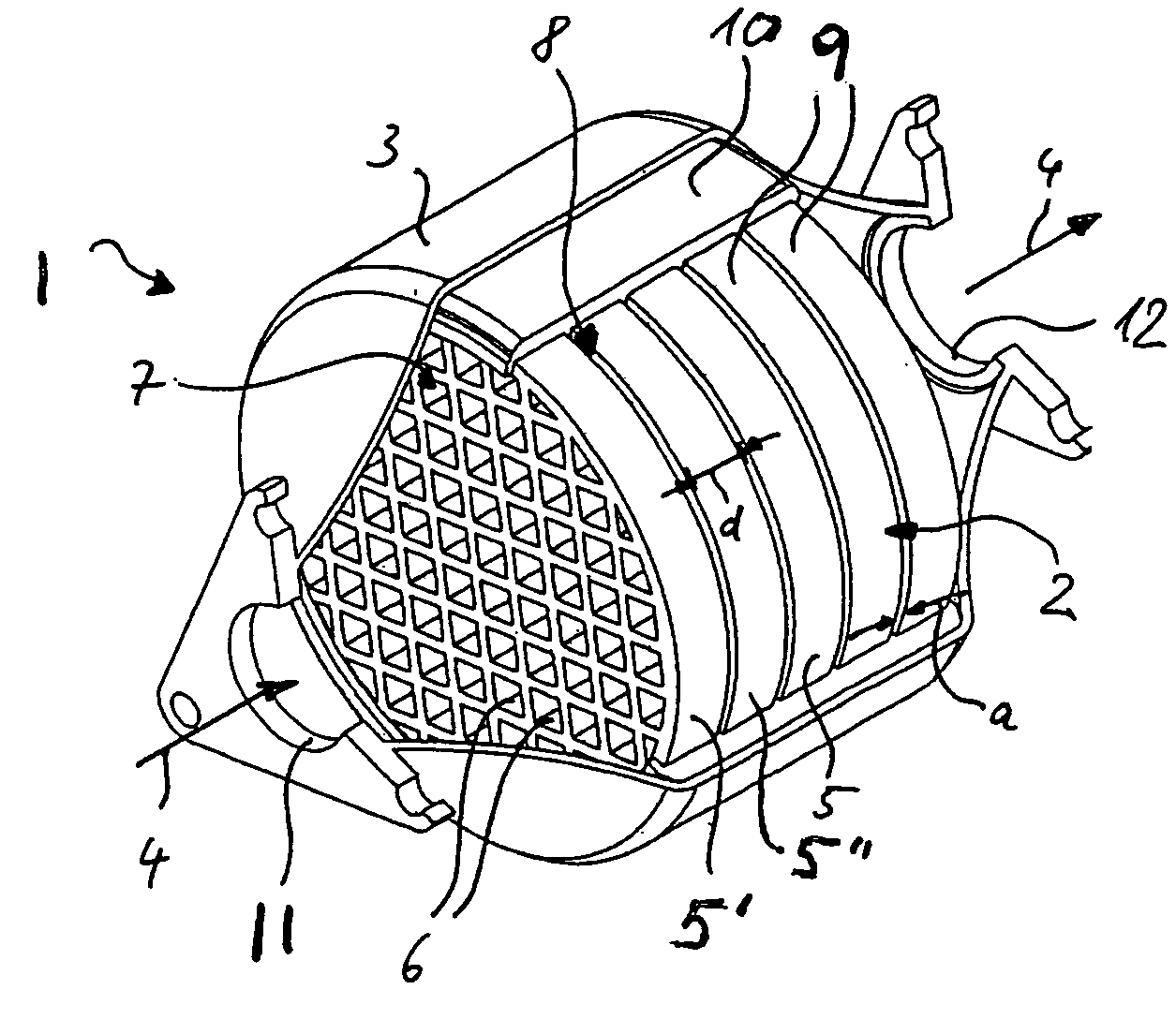
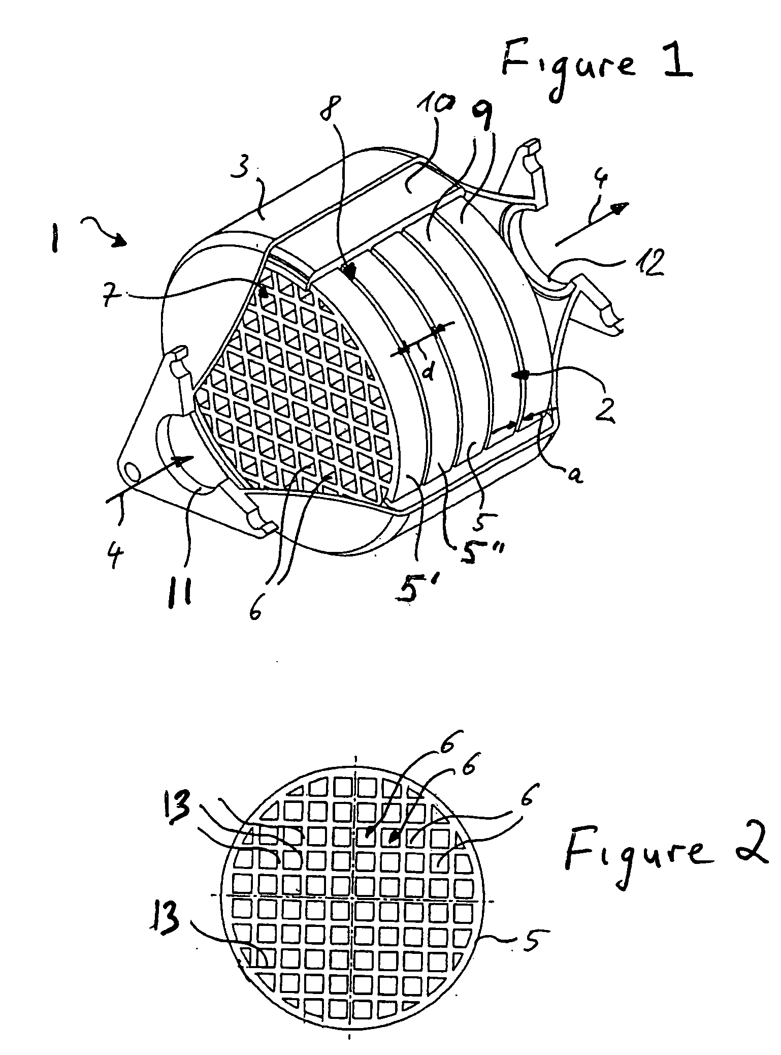
[0021]FIGS. 1 and 2 illustrate an exhaust emission purification device 1 for motor vehicles in accordance with the present invention. As shown, the purification device 1 includes a catalyst body 2 and a housing 3 enclosing the catalyst body 2. Further, the catalyst body 2 includes a plurality of catalyst disks 5 arranged successively in a flow direction 4 of an exhaust gas passing through the purification device 1.

[0022] In addition, each catalyst disk 5 includes flow channels 6 between an intake side 7 and a discharge side 8. The flow channels 6 are bounded by channel walls 13 (see in particular FIG. 2) and extend in the flow direction 4. Further, as shown in FIGS. 1 and 2, the flow channels 6 have a rectangular or honeycomb-shaped cross section and are arranged in an even distribution across the cross-sectional area. Thus, the flow channels 6 allow an exhaust gas to flow from the intake side 7 to the discharge side 8 through each catalyst disk 5. In addition, as a result of a cata...

second embodiment

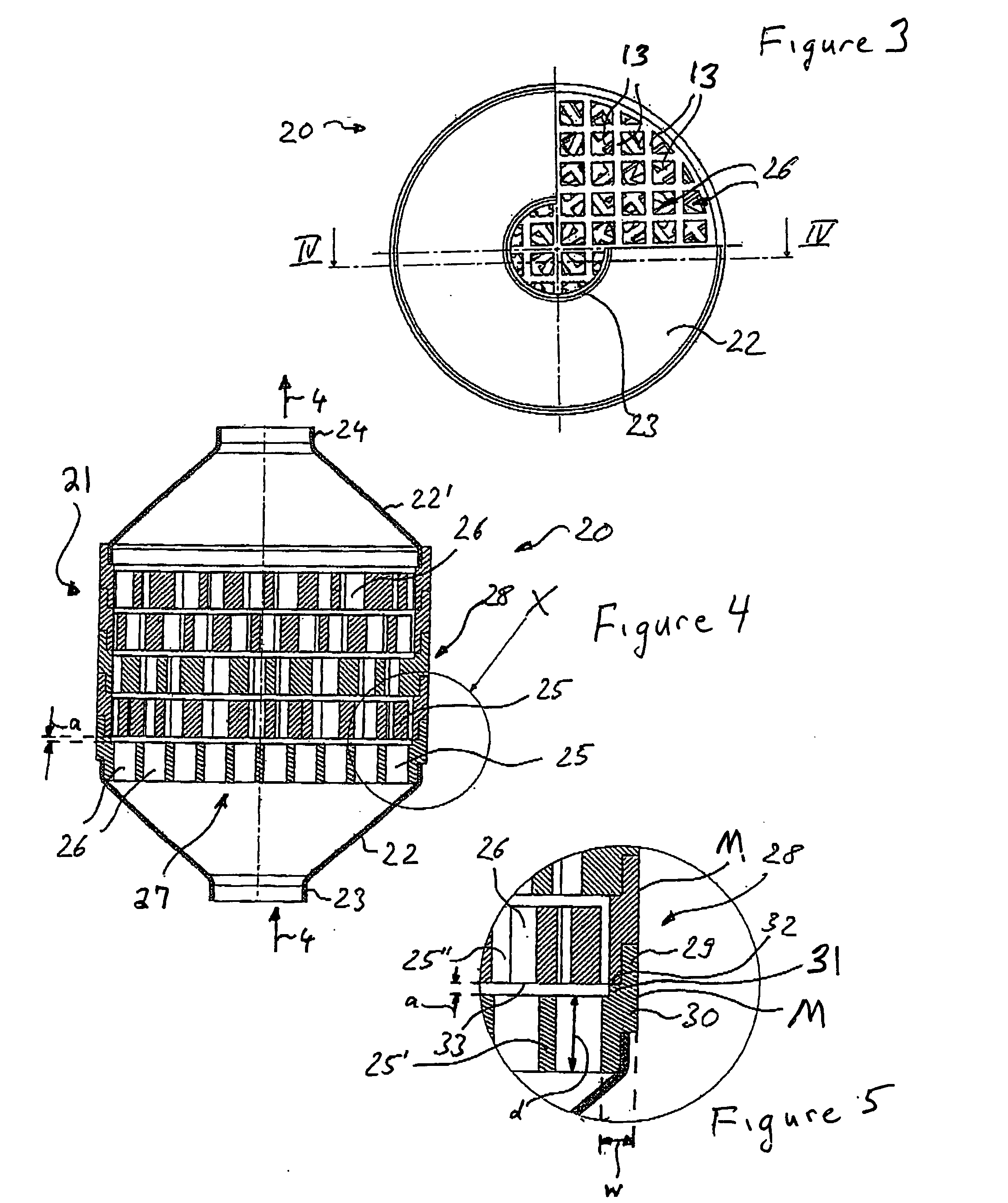
[0034] Also, in accordance with the present invention, adjacent catalyst disks 25 are attached to one another and are attached to the funnel-shaped intake and outlet connecting pieces 23 and 24, respectively, via solder, for example. Alternatively, the catalyst disks 25 can be joined together via a sintering or welding process. In addition, the funnel-shaped intake and outlet connecting pieces 23 and 24 may be connected to the catalyst disks 25 using a subsequent soldering or welding process.

[0035] Further, as shown more clearly in FIG. 4, the catalyst disks 25 are arranged so as to be twisted to one another around a defined angle in a peripheral direction so that the channel walls 13 of adjacent catalyst disks 25 intersect in the flow direction 4. This arrangement increases the generation of turbulences in the exhaust gas flowing through the catalyst body 21. In addition, the catalyst disks 25 may also be produced as described above with respect to the catalyst disks 5 of the first...


PUM

PropertyMeasurementUnit
Thicknessaaaaaaaaaa
Areaaaaaaaaaaa
Distanceaaaaaaaaaa

Abstract

An exhaust emission purification device including a catalyst body with a plurality of flow channels extending between an intake side and a discharge side of the catalyst body. Further, the catalyst body is formed using a sintered catalyst material.

Description

[0001] This non-provisional application claims priority to German Patent Application No. DE 10 2005 017 378.0 filed in Germany on Apr. 14, 2005, and which is herein incorporated by reference.BACKGROUND OF THE INVENTION [0002] 1. Field of the Invention [0003] The present invention relates to an exhaust emission purification device having a catalyst body formed of a sintered catalyst material. [0004] 2. Description of the Background Art [0005] The German Patent Application DE 102 51 624 A1 illustrates an exhaust gas purification device for vehicles, and which includes a tubular housing and a honeycomb-shaped catalyst body. The honeycomb-shaped catalyst body includes a plurality of flow channels extending from an intake side to a discharge side of the catalyst body to thereby allow an exhaust gas to pass through the catalyst body. Further, the flow channels are formed via a plurality of staggered sheet metal layers. The honeycomb-shaped catalyst body also includes a wash-coat layer (ca...

Claims


Application Information

Patent Timeline
IPC IPC(8): B01D50/00
CPCB01J35/0006B01J35/04F01N2330/14B01J37/08F01N3/2803B01J37/0215Y02A50/20
Inventor HEMMATPOUR, YOUSEFSMATLOCH, CHRISTIANHINDER, AXEL
Owner BENTELER AUTOMOBILTECHNIK GMBH
Why Eureka
Try Eureka