Process and apparatus for the manufacture of a sputtering target

a technology of sputtering target and sputtering chamber, which is applied in the field of sputtering target manufacturing process and with, can solve the problems of insufficient room temperature compaction to achieve the required density of the final product, relatively tedious technique, and need to resort to considerably more complex and expensive hot isostatic pressing (hip) sintering techniques

Inactive Publication Date: 2006-10-19
TEKNA PLASMA SYST INC
View PDF11 Cites 21 Cited by
  • Summary
  • Abstract
  • Description
  • Claims
  • Application Information

AI Technical Summary

Benefits of technology

[0006] An object of the present invention is therefore to provide improved process and apparatus for the manufacture of sputtering targets.

Problems solved by technology

The technique is relatively tedious and requires a number of steps for the powder preparation and densification, followed by powder compaction at room temperature and subsequent sintering to the required high-density level.
In certain cases, room temperature compaction is not sufficient to achieve the required density of the final product.
In such cases, it is necessary to resort to the considerably more complex and expensive Hot Iso-static Pressing (HIP) sintering techniques.

Method used


Image

  • Process and apparatus for the manufacture of a sputtering target
  • Process and apparatus for the manufacture of a sputtering target
  • Process and apparatus for the manufacture of a sputtering target

Examples


Embodiment Construction

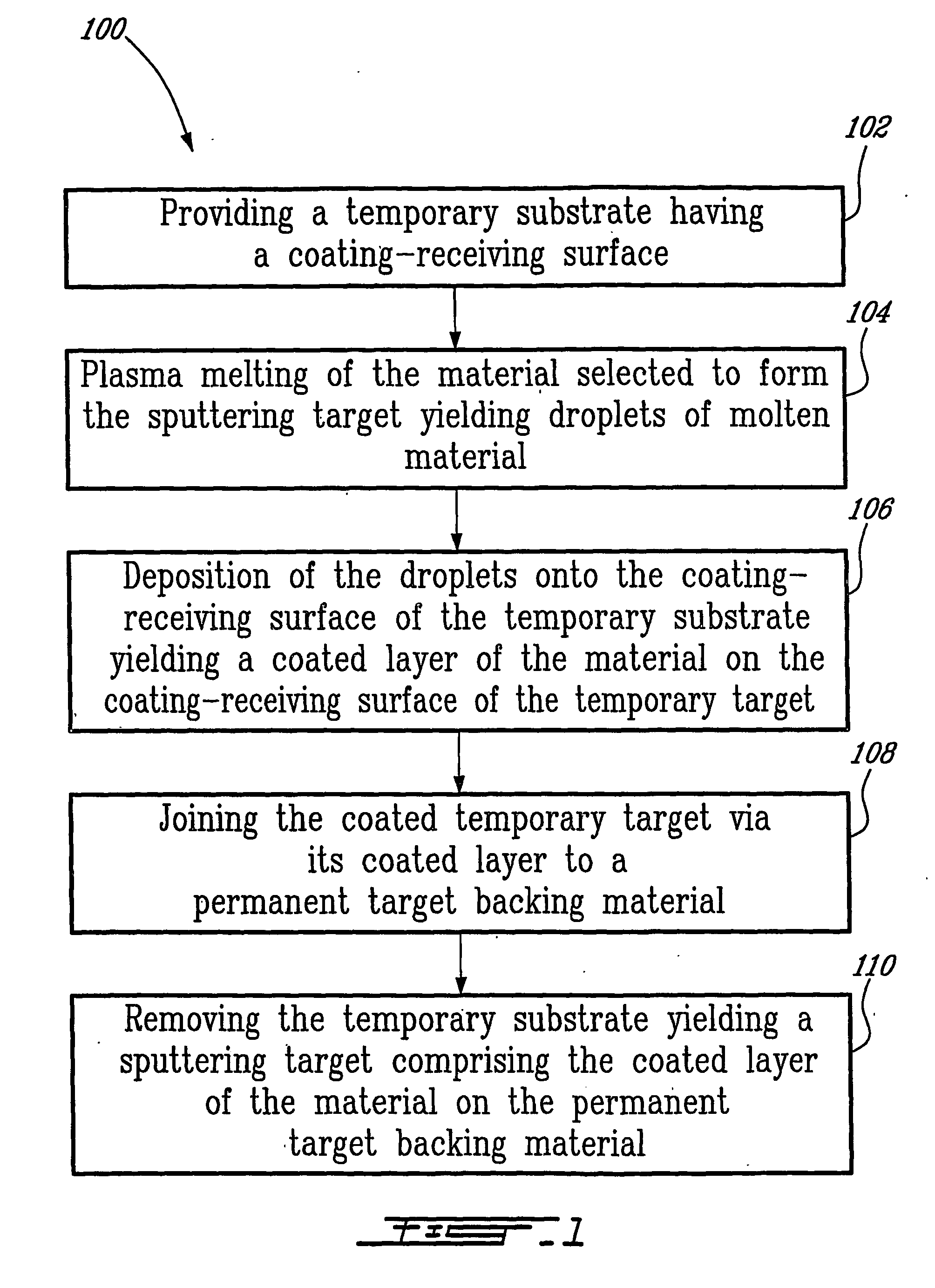
[0030] A process 100 for the manufacture of sputtering targets according to an illustrative embodiment of a first aspect the present invention will now be described with reference to FIGS. 1-3.

[0031] As illustrated in FIG. 1, the process 100 includes the following steps:

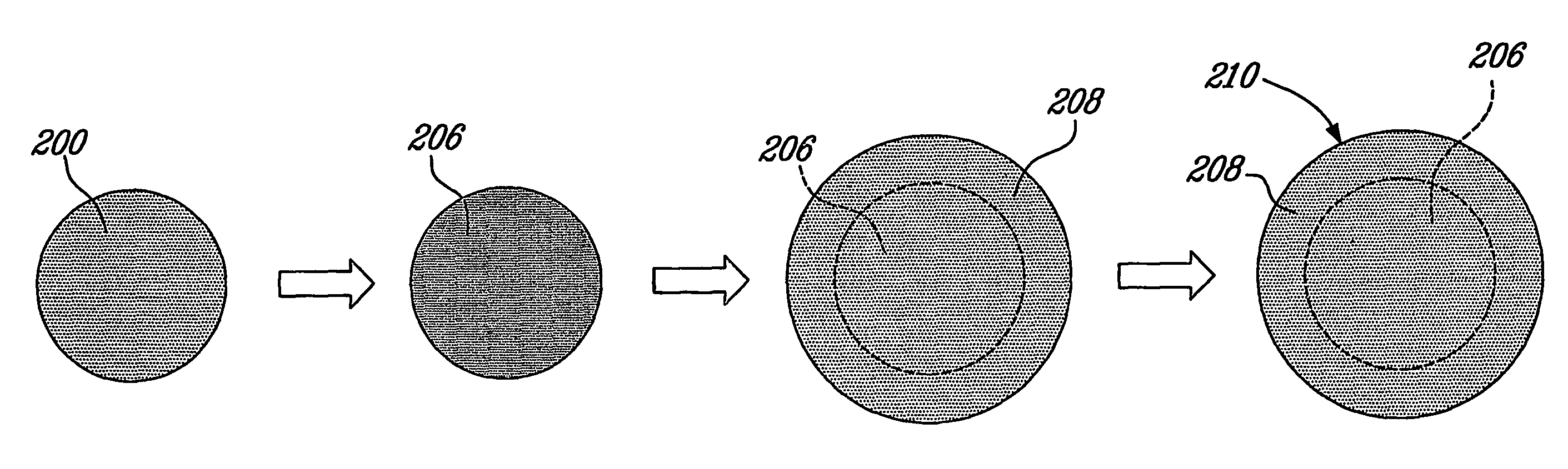
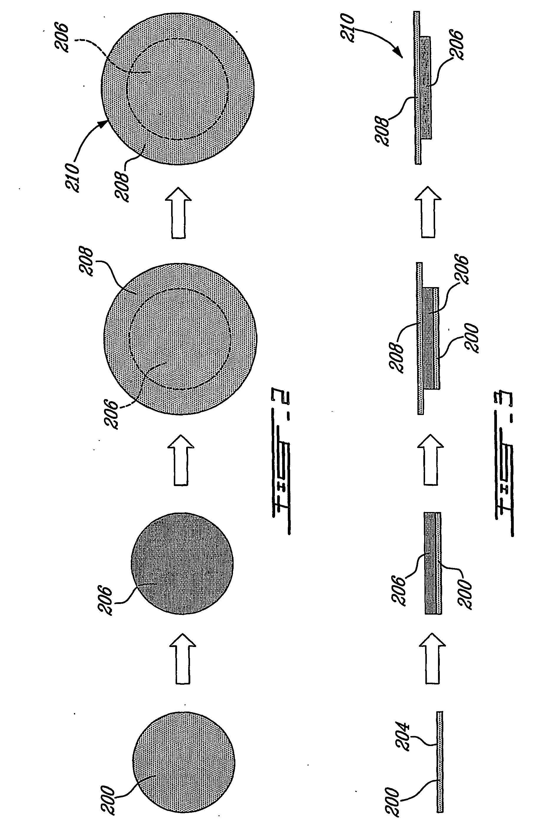
[0032]102—providing a temporary substrate 200 having a coating-receiving surface 204;

[0033]104—plasma melting of the material selected to form the sputtering target, yielding droplets of molten material;

[0034]106—deposition of the droplets onto the coating-receiving surface 204 of the temporary substrate 200, yielding a coated layer 206 of the material on the coating-receiving surface 204 of the temporary target 200;

[0035]108—joining the coated temporary target via its coated layer 206 to a permanent target backing material 208; and

[0036]110—removing the temporary substrate 200, yielding a sputtering target 210 comprising the coated layer of the material 206 on the permanent target backing material 208.

[0037] ...


PUM

PropertyMeasurementUnit
densityaaaaaaaaaa
stress reliefaaaaaaaaaa
stressaaaaaaaaaa

Abstract

A process for the manufacture of sputtering target comprises the steps of i) providing a substrate; ii) plasma melting of a material selected to form the sputtering target, yielding droplets of molten material; and iii) deposition of the droplets onto the substrate, yielding a sputtering target comprised of the coated layer of the material on the substrate. In some application, it might be preferable that the substrate be a temporary substrate and iv) to join the coated temporary target via its coated layer to a permanent target backing material; and v) to remove the temporary substrate, yielding a sputtering target comprised of the coated layer of the material on the permanent target backing material. The plasma deposition step is carried out at atmospheric pressure or under soft vacuum conditions using, for example, d.c. plasma spraying, d.c. transferred arc deposition or induction plasma spraying. The process is simple and does not require subsequent operation on the resulting target.

Description

FIELD OF THE INVENTION [0001] The present invention relates to sputtering targets. More specifically, the present invention is concerned with a process for the manufacture of sputtering targets and with an apparatus therefore. BACKGROUND OF THE INVENTION [0002] Sputtering targets are essential components in the thin film coating industry. They are used as a source of high purity materials, which are released from the target surface as a result of its bombardment with energetic projectile particles such as an ion beam. The particles that are released, in the form of vapours, are subsequently directed towards the surface of a substrate where they are deposited in the form of a thin film of controlled thickness and purity. The most striking characteristic of the sputtering process is its universality. Virtually any material can be a coating candidate since it is passed into the vapour phase by a physical momentum-exchange rather than a chemical or thermal process. [0003] Thin film depo...

Claims


Application Information

Patent Timeline
Patent Type & Authority Applications(United States)
IPC IPC(8): B05D1/08H05H1/24C23C14/00C23C4/12C23C4/18C23C14/34
CPCC23C4/12C23C4/127H01J37/3491C23C14/3414C23C4/185C23C4/134Y02T50/60
Inventor BOULOS, MAHER I.JUREWICZ, JERZY W.
Owner TEKNA PLASMA SYST INC
Why Eureka
Try Eureka