Earth boring tool

a drilling tool and earth technology, applied in the direction of drilling machines, borehole drives, cutting machines, etc., can solve the problems of reducing the wear resistance of pdc cutters, increasing the risk of abrasion, and affecting the use of earth boring tools, so as to reduce wear and other adverse effects, increase the tangential velocity of cutters, and reduce the effect of wear

Inactive Publication Date: 2006-10-26
DENNIS TOOL
View PDF8 Cites 96 Cited by
  • Summary
  • Abstract
  • Description
  • Claims
  • Application Information

AI Technical Summary

Benefits of technology

[0011] The invention pertains to an earth boring tool, or aspects thereof, having PDC cutters that overcomes one or more of these problems by combining on the same rotational axis a central bit and a relatively larger diameter reamer that extends beyond the central bit. In effect, the central bit bores the center of the hole and the reamer enlarges it. By turning the reamer at a relatively low angular velocity relative to the earth, the tangential velocity of the cutters on the reamer are kept low enough to reduce wear and other adverse affects associated with higher tangential velocities of the cutters. The central bit is allowed to rotate relatively faster, thereby permitting larger diameter holes to be bored without adversely affecting cutter performance or drilling rate. Cutting speed can be optimized, allowing the maximum efficiency without excess wear of the cutters.
[0012] Several additional benefits are possible with such a tool. It will tend to create less vibration and chatter. Less force on the drilling tool is required for cutting. This in turn lowers the torque on the drill string, lessening the chance of the drill string of wrapping up. Lighter force applied to the tool also permits use of a lighter tubing having thinner walls to be used.

Problems solved by technology

Although PDC cutters are known to have one of the lowest rates of wear when operated at cooler temperatures, thermal damage to the diamond layer of the cutter begins at temperatures of approximately 700 degrees Celsius.
Thermal damage lowers wear resistance and the PDC cutters become more susceptible to abrasive wear and breakage from impact.
At some velocity, frictional heat reaches a level sufficient to cause cutter wear rates to accelerate, reducing the life of the cutters.
Thus, a PDC cutter's intolerance of high temperatures limits, in practice, the diameter of the bit.
Cutters dragging through harder rock have higher wear rates due to the increased application of force.
A number of additional factors also shorten the life of PDC cutters.
First, a cutter's abrupt contact with rock formations also increases the rate of wear of PDC cutters.
These irregular contacts can cause impact damage to the cutters.
Second, drill strings will also vibrate, sometimes severely.
These vibrations can also damage a drill bit, including the cutters, as well as the drill pipe, MWD equipment, and other components in the drilling system.
Third, “bit whirl” further contributes to impact loads on PDC cutters.
Cutters on these drill bits will lose large chips of PDC from impact, rather than from gradual abrasion of the cutter, thereby shortening the effective life of the cutters and the drill bit.

Method used


Image

  • Earth boring tool
  • Earth boring tool
  • Earth boring tool

Examples


Embodiment Construction

[0017] In the following description, like numbers throughout the figures refer to like elements.

[0018] Briefly, in the following example of an earth boring tool, the pilot bit and reamer are each driven by a separate motor, thereby avoiding the complexities of gears and problems occasioned by them. Examples of such problems include structural complexities necessary to have seals, with the attendant potential for failure. If seals are not used, there is a substantial risk of gear failure or jamming that is not easily addressed by merely hardening the gears.

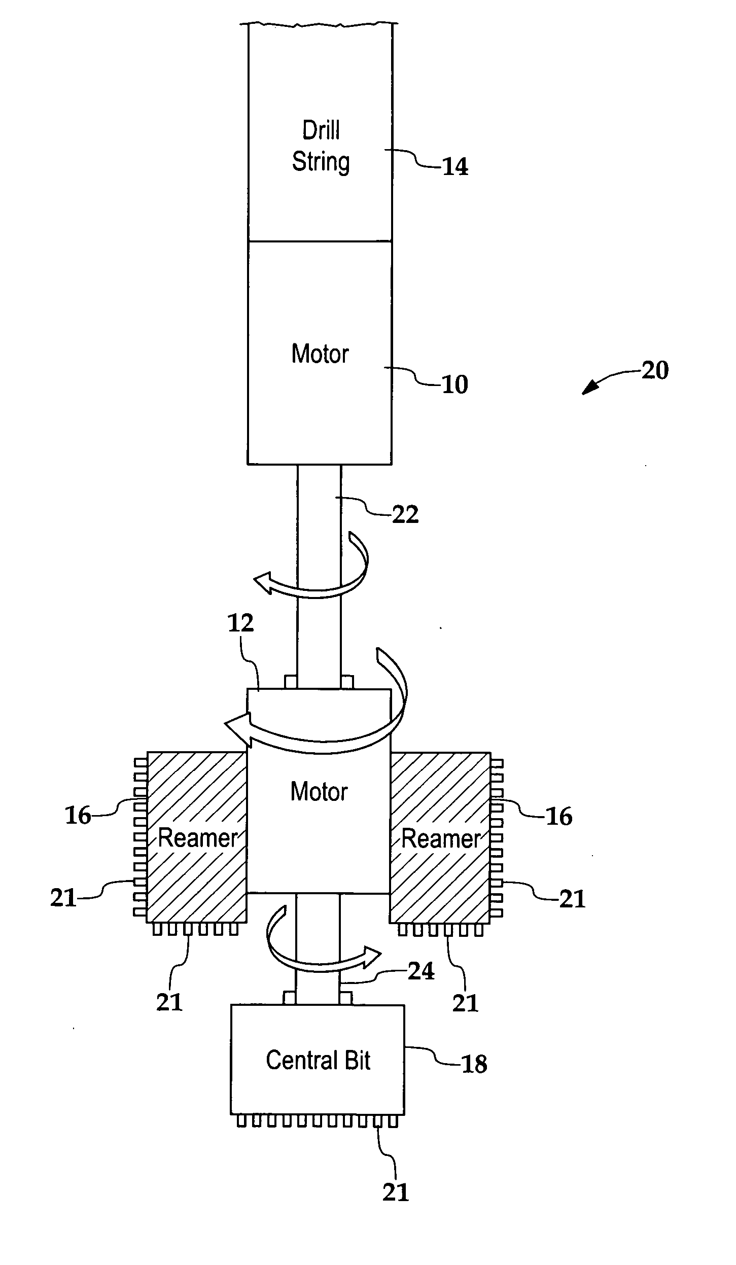
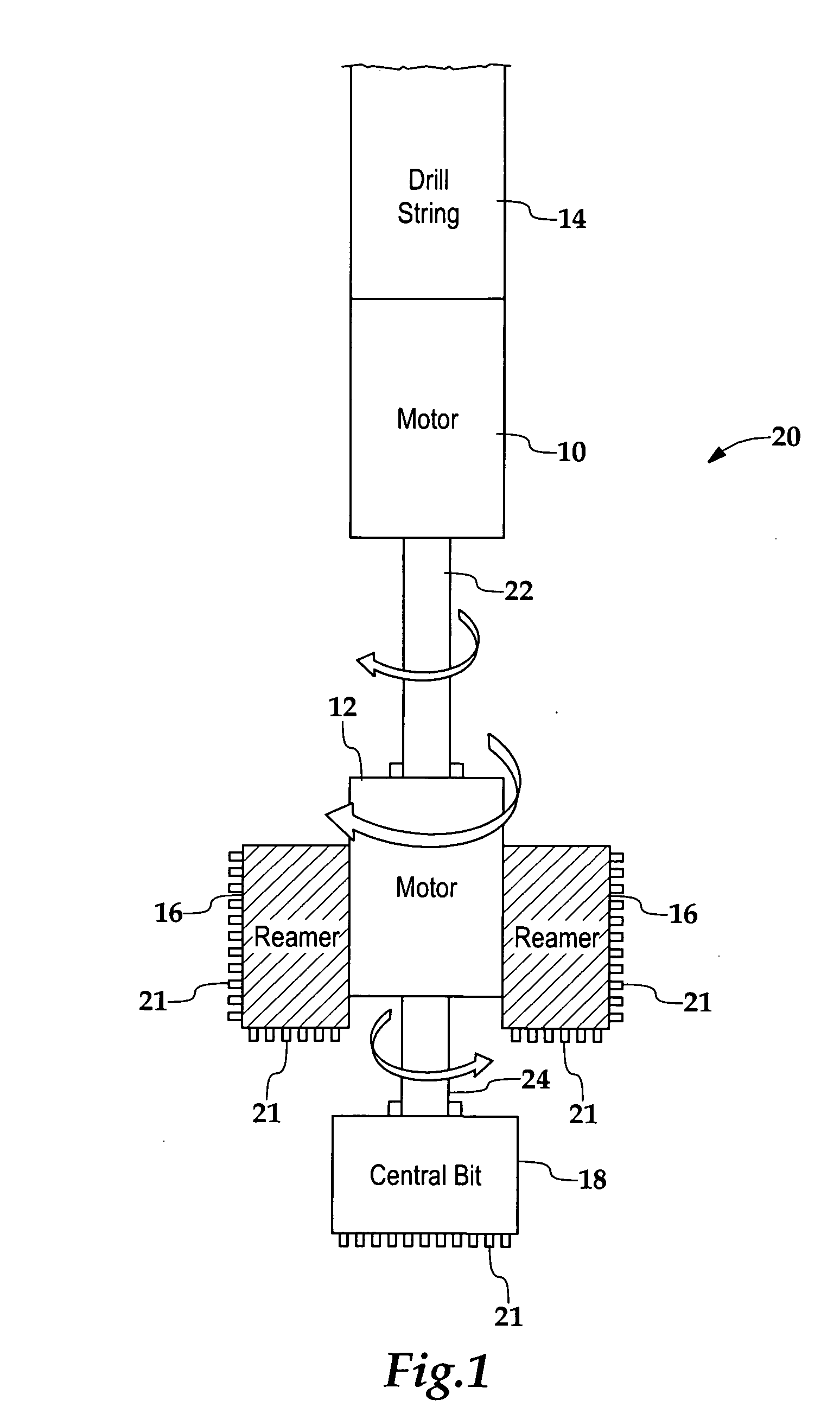
[0019]FIG. 1 schematically illustrates the functional and spatial relationships between two motors 10 and 12, a drill string 14, reamer 16 and a central bit 18 within an earth boring tool 20. The reamer and central bit each possess a plurality of cutters 21 along exterior cutting surfaces. The central bit drills a pilot hole; the sleeve-shaped or donut-shaped reamer, since it has an wider diameter, widens the hole. These cutters ...


PUM


Abstract

An earth boring tool includes two coaxially-aligned, positive displacement motors. One motor turns a pilot bit and the other turns a reamer concentric with the pilot bit. The central bit bores the center of the hole and the reamer enlarges it. The central bit is rotated relatively faster, while rotation of the larger diameter reamer is relatively slow. The tool can thus be used to bore larger diameter holes without slowing drilling rates or adversely affecting performance of the cutter elements due to higher tangential velocities.

Description

BACKGROUND OF THE INVENTION [0001] The invention relates to tools for forming bores in the earth, especially rock, and particularly to rotary drill bits for use in oil and gas exploration and mining. [0002] Drag bits for drilling through rock are typically outfitted with hard, durable cutters. To improve wear, the cutters often possess contact surfaces made from diamond, typically in the form of polycrystalline diamond compact (PDC). PDC is an extremely hard and wear resistant material. [0003] Although PDC cutters are known to have one of the lowest rates of wear when operated at cooler temperatures, thermal damage to the diamond layer of the cutter begins at temperatures of approximately 700 degrees Celsius. Thermal damage lowers wear resistance and the PDC cutters become more susceptible to abrasive wear and breakage from impact. [0004] Greater tangential cutter velocity causes more friction, thus generating more heat. Cutters moving at higher tangential velocities will thus tend ...

Claims


Application Information

Patent Timeline
Patent Type & Authority Applications(United States)
IPC IPC(8): E21B10/36E21B4/00E21B10/26
CPCE21B4/02E21B10/26E21B7/28E21B4/16
Inventor DENNIS, MAHLON D.DENNIS, THOMAS M.TWARDOWSKI, ERIC M.POWELL, ROY
Owner DENNIS TOOL
Why Eureka
Try Eureka