Gaseous fluid metering valve

a gaseous fluid and metering valve technology, applied in the direction of valve operating means/release devices, machines/engines, transportation and packaging, etc., can solve the problems of undesirable requirement, undesirable nox gas formation, etc., and achieve high flow rate, long operating stoke, and high operating force

Inactive Publication Date: 2006-10-26
BORGWARNER INC
View PDF61 Cites 17 Cited by
  • Summary
  • Abstract
  • Description
  • Claims
  • Application Information

AI Technical Summary

Benefits of technology

[0009] The invention disclosed is an EGR valve that will provide high operating force, longer operating stoke, and high flow rate. The rotary motion is converted to axial motion through a unique high efficiency actuator that provides movement of the valves. Another desirable feature of the invention is a self-cleaning action of the valves due to the rotational movement of the shaft as it moves the valve between the open and closed position.

Problems solved by technology

Formation of undesirable NOx gas will occur when there is a high combustion temperature inside of the engine.
Pneumatically actuated valves depend upon the availability of pressure or vacuum on the vehicle and this may be an undesirable requirement.
Additionally, contamination in the exhaust gas can accumulate on the valve components and cause them to stick if sufficient operating force is not available.

Method used


Image

  • Gaseous fluid metering valve
  • Gaseous fluid metering valve
  • Gaseous fluid metering valve

Examples


Embodiment Construction

[0017] The following description of the preferred embodiment(s) is merely exemplary in nature and is in no way intended to limit the invention, its application, or uses.

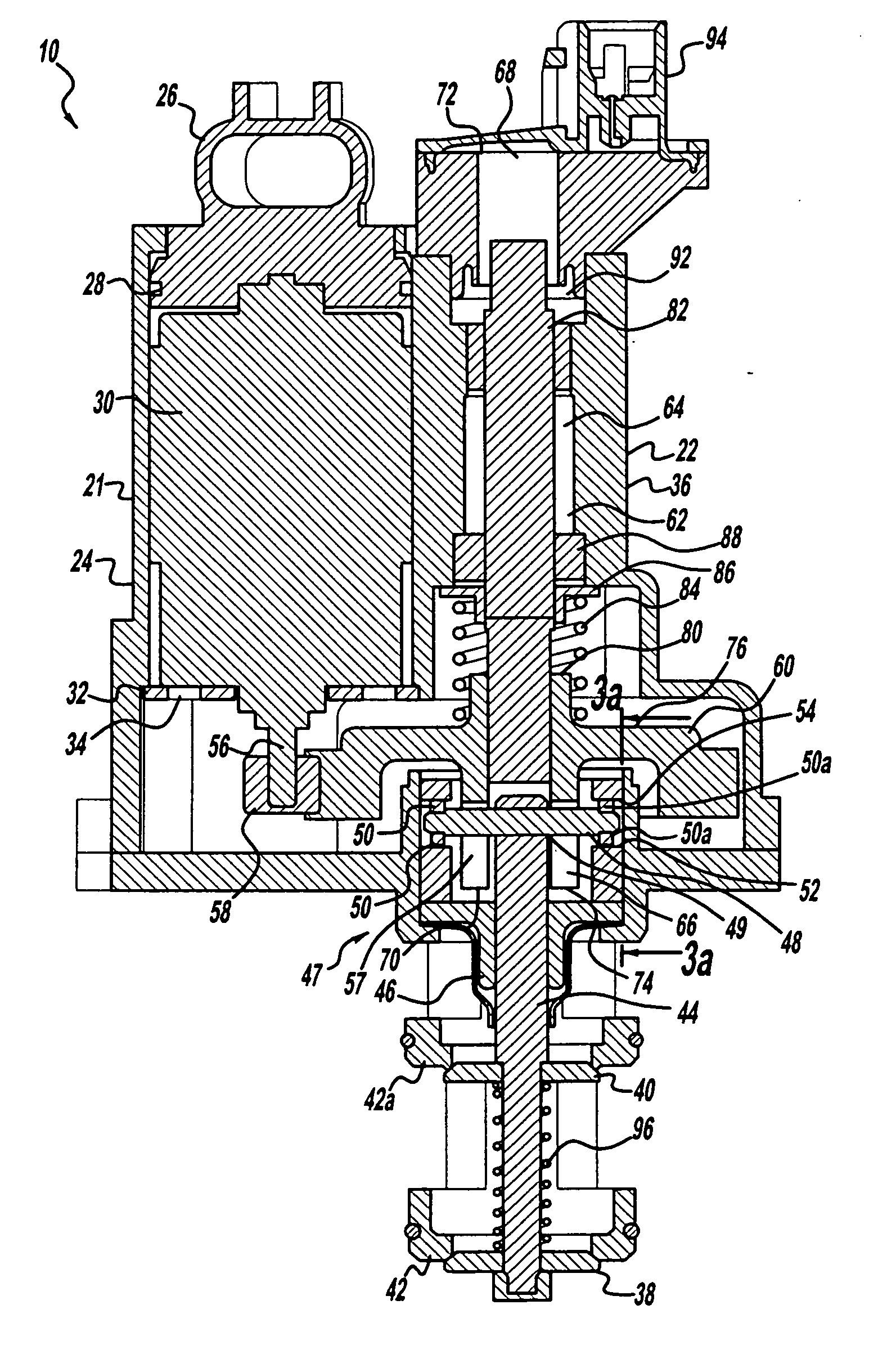
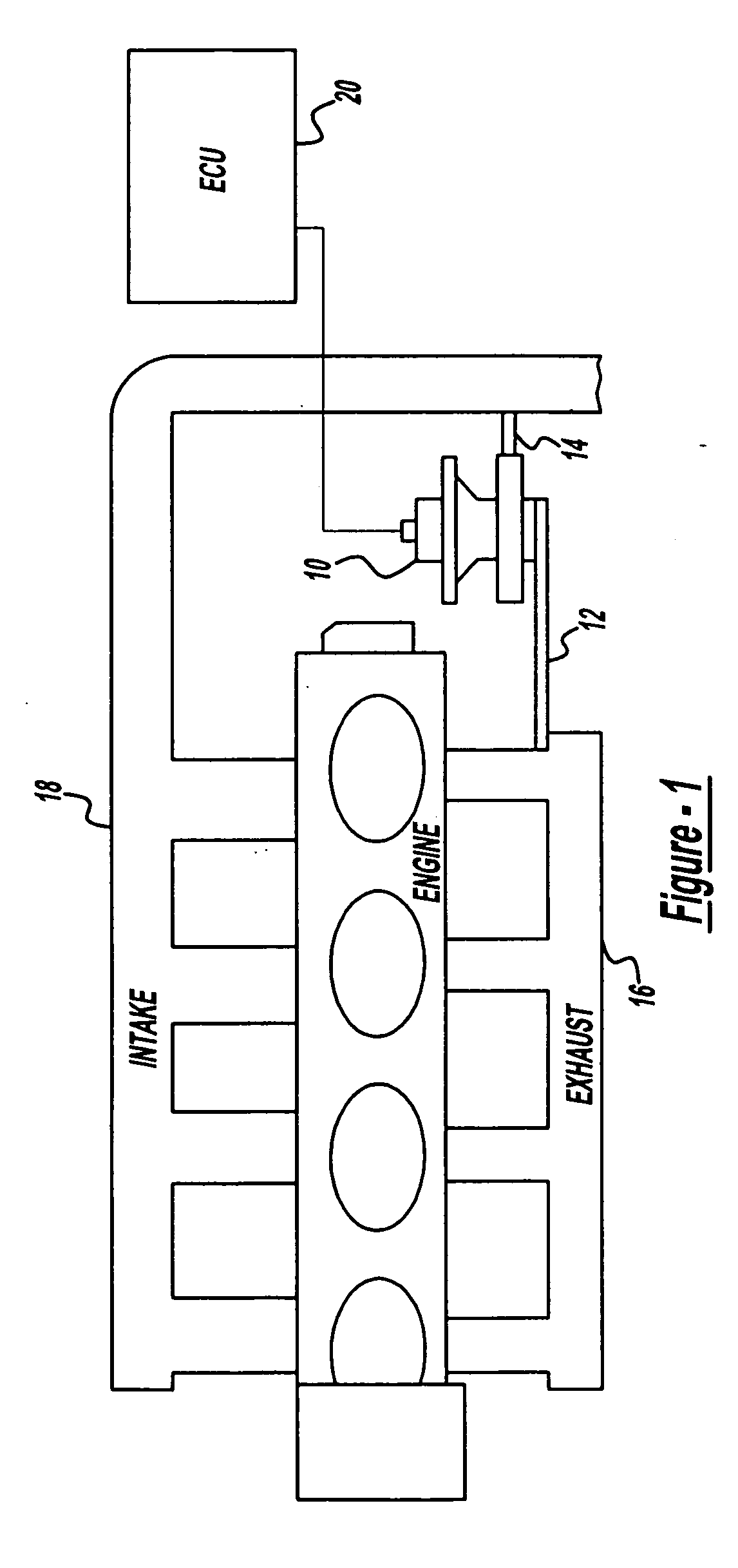
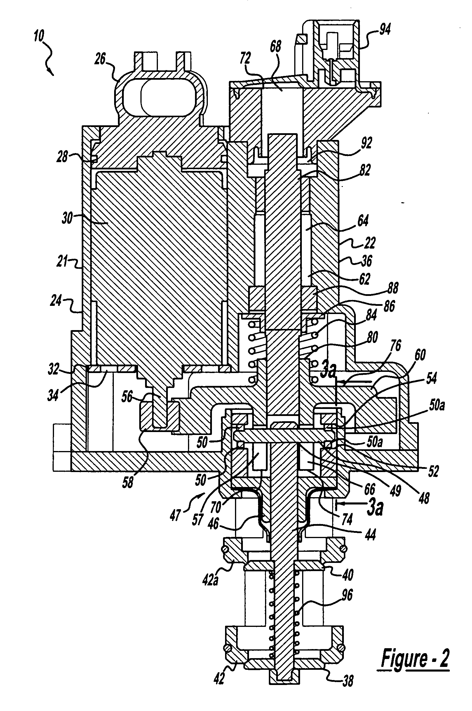
[0018] Referring to FIG. 1 a schematic diagram of an EGR system is depicted in accordance with the present invention. The system consists of an exhaust gas recirculation (EGR) valve 10 that controls the flow of exhaust gas to an intake manifold 18. An input passage 12 is connected between the EGR valve 10 and an exhaust manifold 16 of the engine. An output passage 14 is located between the EGR valve 10 and the intake manifold 18 of the engine. The input passage 12 and the output passage 14 serve as an interconnection allowing the EGR valve 10 to effectively control the flow of the exhaust gas in the engine.

[0019] The EGR valve 10 is an electronically controlled valve that is controlled by an engine control unit (ECU) 20. The ECU 20 provides a signal that will control the opening, closing and intermediate positionin...


PUM


Abstract

The present invention is directed to an exhaust gas recirculation valve incorporating a DC motor and a dual poppet valve assembly. A motor is contained inside of the actuator housing. The motor has a rotatable motor shaft with a first gear connected to the end of the motor shaft. A second gear is engageable to the first gear and is configured to rotate in response to the movement of the first gear and the motor shaft. The second gear is also connected to a pin member disposed through the top portion of a shaft member that has two poppet valves disposed on to the shaft. The two ends of the pin member are slidably engageable to either an upwardly or downwardly sloped ramp portion. When the second gear rotates the shaft rotates and moves upward or downward to cause the valve members to move between an open and closed position.

Description

CROSS-REFERENCE TO RELATED APPLICATIONS [0001] This application claims the benefit of U.S. Provisional Application No. 60 / 393,459, filed Jul. 2, 2002.FIELD OF THE INVENTION [0002] The present invention relates to a gaseous fluid metering valve for use in a vehicle. More particularly the present invention relates to a high flow exhaust gas recirculation (EGR) valve for an engine of a vehicle. BACKGROUND OF THE INVENTION [0003] Federal and State legislation require control of vehicle exhaust emissions. Oxides of Nitrogen (NOx) are among the exhaust gas emissions that must be controlled. Formation of undesirable NOx gas will occur when there is a high combustion temperature inside of the engine. In an effort to remove or reduce combustion temperatures and NOx emissions, exhaust gas recirculation (EGR) valve systems have been developed. EGR valves function by recirculating a portion of the exhaust gas back to the intake manifold where it will be combined with incoming outside air. The m...

Claims


Application Information

Patent Timeline
Patent Type & Authority Applications(United States)
IPC IPC(8): F16K31/02F02M25/07
CPCF02M25/0701F02M25/0773Y02T10/121F02M25/0792F02M25/0789F02M26/69F02M26/50F02M26/54F02M26/67Y10T137/428
Inventor TELEP, ROBERT J.KEEFOVER, ROBERT D.HALSIG, MICHAEL J.
Owner BORGWARNER INC
Why Eureka
Try Eureka