LED current bias control using a step down regulator

Active Publication Date: 2006-10-26
SEMICON COMPONENTS IND LLC
View PDF9 Cites 69 Cited by
  • Summary
  • Abstract
  • Description
  • Claims
  • Application Information

AI Technical Summary

Benefits of technology

[0016] Conventional switching regulator circuits require complex current monitoring circuitry and feedback control logic to generate a desired average load current. By using a simple control circuit to maintain the conduction mode at the crossover point between continuous conduction mode and discontinuous conduction mode, the average load current can be easily predicted, thereby eliminating the need for a PWM control signal and attendant current monitor

Problems solved by technology

However, once the magnetic field in the inductor collapses, the Schottk

Method used


Image

  • LED current bias control using a step down regulator
  • LED current bias control using a step down regulator
  • LED current bias control using a step down regulator

Examples


Embodiment Construction

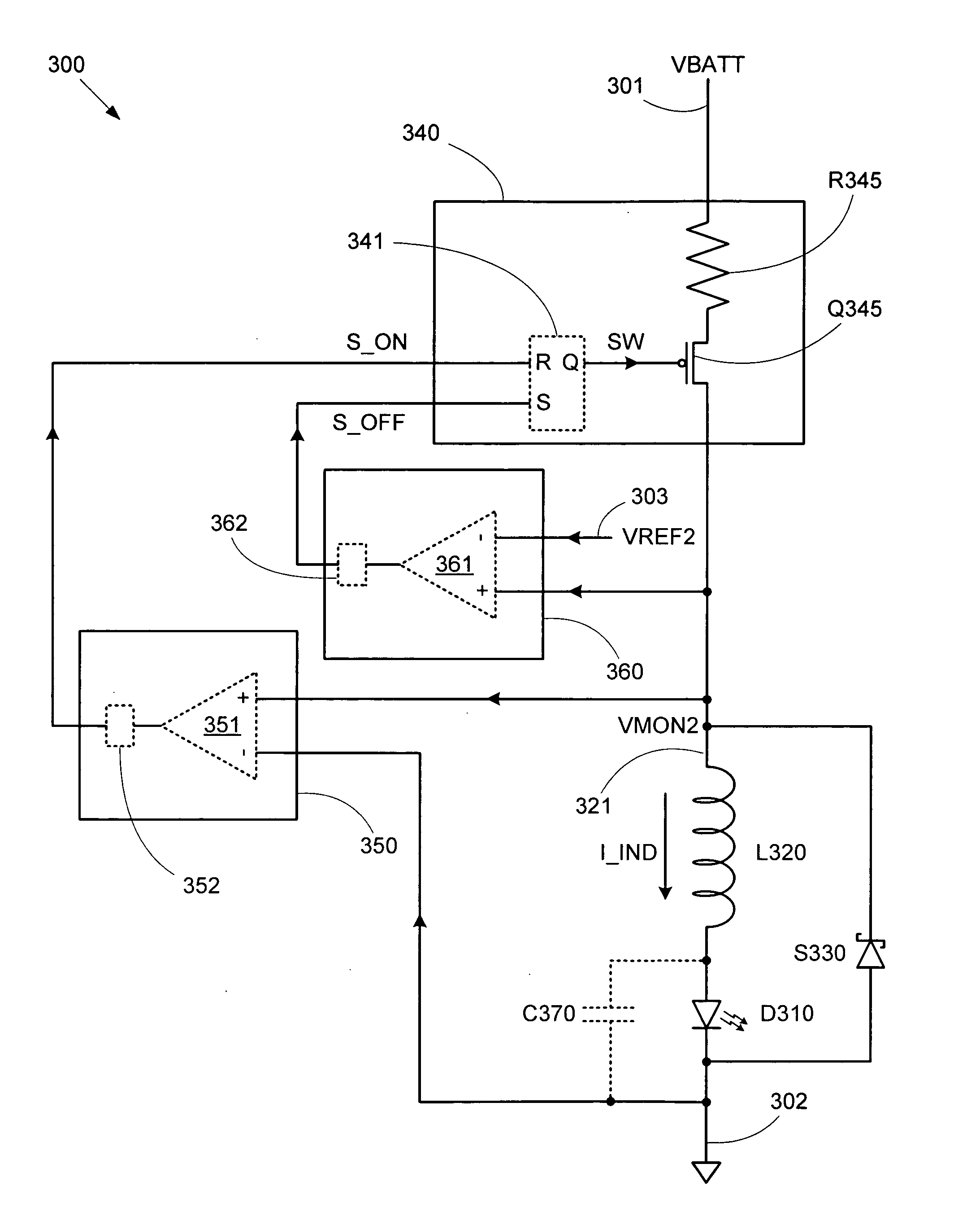
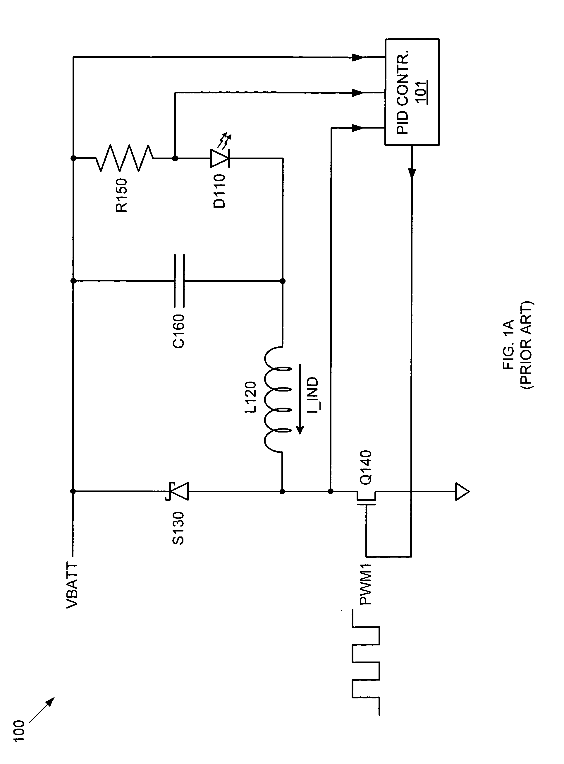
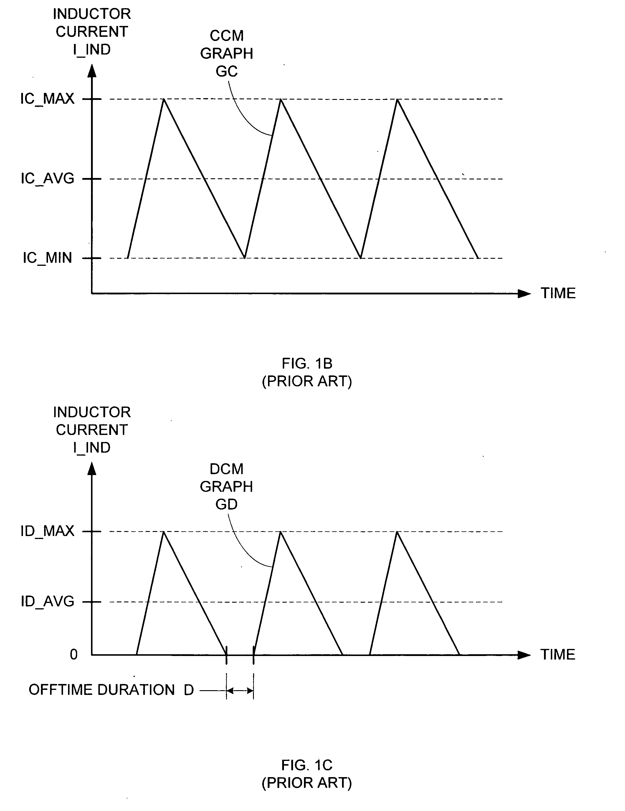
[0028] Conventional switching regulator circuits require complex current monitoring circuitry and feedback control logic to generate a desired average load current. By using a simple control circuit to maintain the conduction mode at the crossover point between continuous conduction mode and discontinuous conduction mode, the average load current can be easily predicted, thereby eliminating the need for a PWM control signal and attendant current monitoring circuitry can be eliminated. Furthermore, by operating at this crossover conduction mode (XCM) in which the minimum load current is zero, the average current delivered by a switching regulator operated in this manner is simply a function of the maximum inductor current. Therefore, only the maximum inductor current need be defined to cause the switching regulator circuit to provide a desired average load current, thereby greatly simplifying configuration requirements.

[0029]FIG. 2 shows a circuit diagram of a step down switching re...


PUM


Abstract

A step down switching regulator circuit that is particularly well-suited to drive high power LEDs includes a crossover conduction mode (XCM) control circuit that maintains operation at the crossover point between continuous conduction mode (CCM) and discontinuous conduction mode (DCM). This XCM operation provides an inductor current waveform that ramps up and down between zero and a desired maximum current. One or more comparators in the XCM control circuit can be used to control switching between the inductor current ramp up and ramp down phases. In this manner, complex feedback loop logic and PID controlled PWM signal generation logic can be avoided, and the need for external sense resistors and associated interface pins can be eliminated.

Description

BACKGROUND OF THE INVENTION [0001] 1. Field of the Invention [0002] The invention relates to the field of electronic circuits, and in particular, to a circuit for providing accurate current bias control for light emitting diode applications. [0003] 2. Related Art [0004] A light emitting diode (LED) is a diode that emits photons in response to a current flow between its anode and cathode. LEDs are often used in modern lighting applications due to their durability, efficiency, and small size compared to other light sources. The range of applications for which LEDs are appropriate is continually increasing due to development of increasingly higher efficiency and higher output LEDs. For example, many types of automotive lighting elements (e.g., interior lights, external signal lights) are being updated with LED sources. [0005] To properly power the LEDs in these high-power applications (i.e., applications in which a significant voltage difference exists between the load voltage (e.g., r...

Claims


Application Information

Patent Timeline
IPC IPC(8): G05F1/613H01L33/00
CPCH05B33/0818H05B45/375G05F1/613
Inventor RUSSELL, ANTHONY G.BARTHOLOMEUSZ, CHRIS B.
Owner SEMICON COMPONENTS IND LLC
Why Eureka
Try Eureka