Speckle reduction optical mount device

Inactive Publication Date: 2006-10-26
HITACHI SEIKO LTD
View PDF4 Cites 44 Cited by
  • Summary
  • Abstract
  • Description
  • Claims
  • Application Information

AI Technical Summary

Benefits of technology

[0010] The HOE or DOE shaper located in this mount is placed within a beam delivery system used for focal point machining or mask imaging. The mount is then connected to the motion controller and laser pulsing circuit to allow for either open or closed

Problems solved by technology

Such beam shaping, however, generally results in “speckling” of the energy distribution of the shaped beam wherein speckle looks like a grainy pattern across the shaped beam area at the image plane.
This is compounded by beam shaping with HOE or DOE elements which result in speckle patterns due to superposition of mode field patterns.
When drilling microvias in differing material layers or laminations, the speckle pattern could be significant enough to create partial drilling of the material leaving an undesirable level of surface texture and roughness or partial drilling of features, which either requires more laser pulses or the need for trepanning the laser beam to average out the speckle pattern.
Trepanning significantly increases the time to produce the microvias which translates into more time and co

Method used


Image

  • Speckle reduction optical mount device
  • Speckle reduction optical mount device
  • Speckle reduction optical mount device

Examples


Example

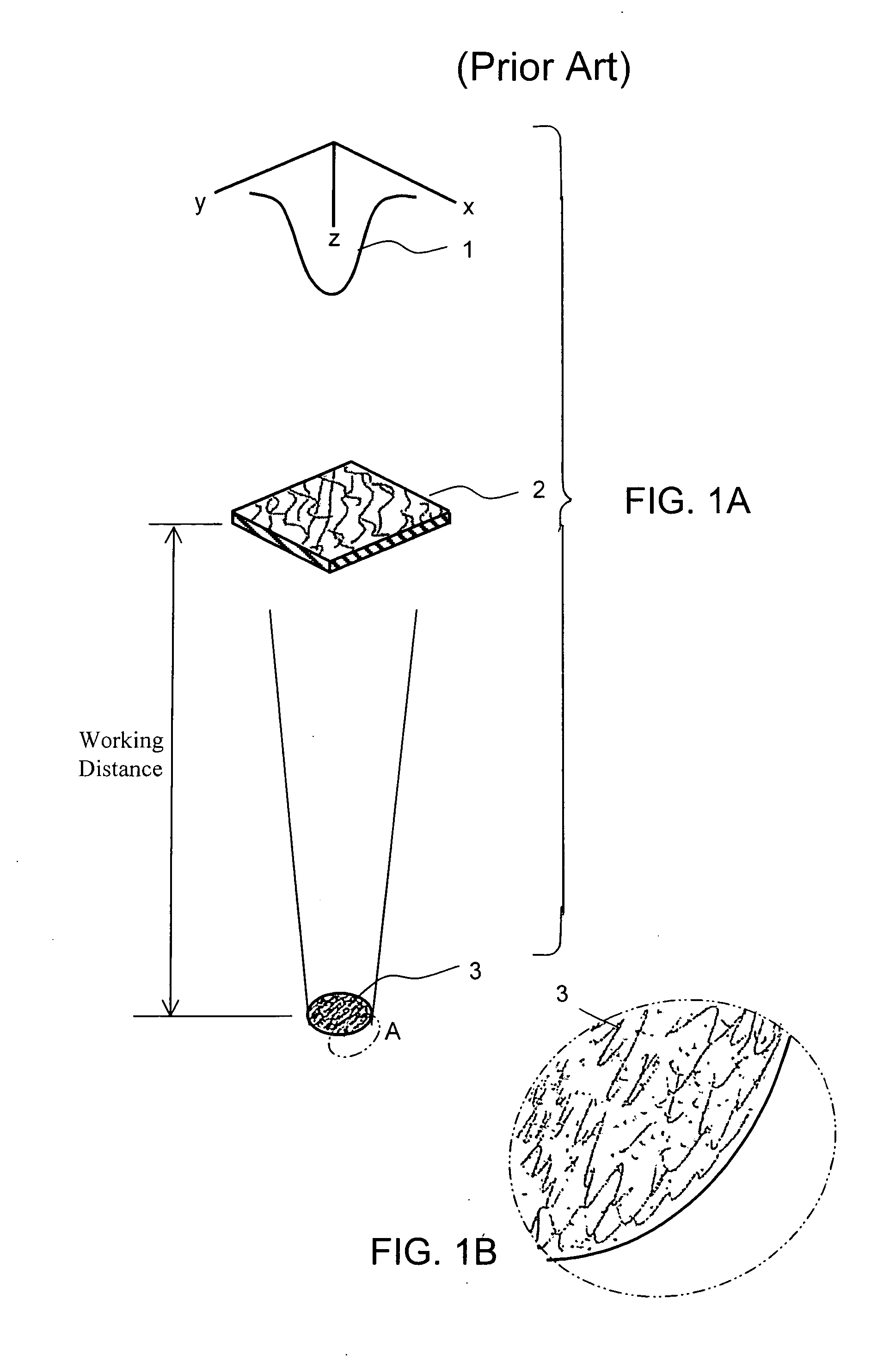
[0024]FIG. 1A shows a Computer Generate Hologram Beam Shaper (CGH) 2 being illuminated by a Gaussian Beam 1 wherein the CGH is transforming the beam 1 into a shaped image 3 at the image plane and where the speckle pattern that develops in the shaped image 3 is illustrated, in further detail in FIG. 1B.

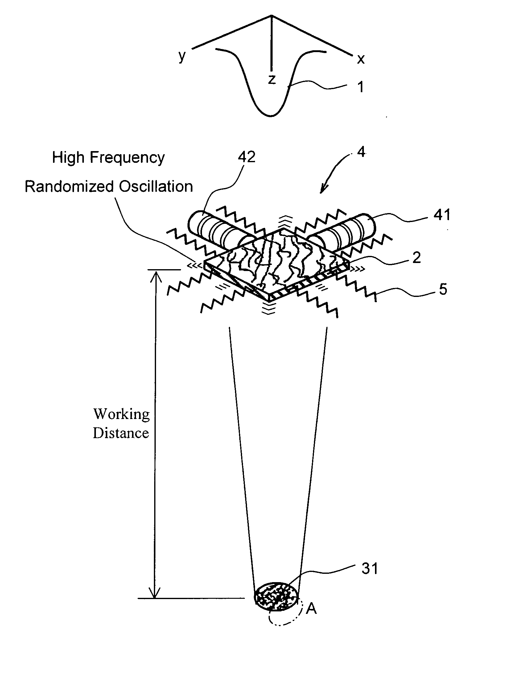
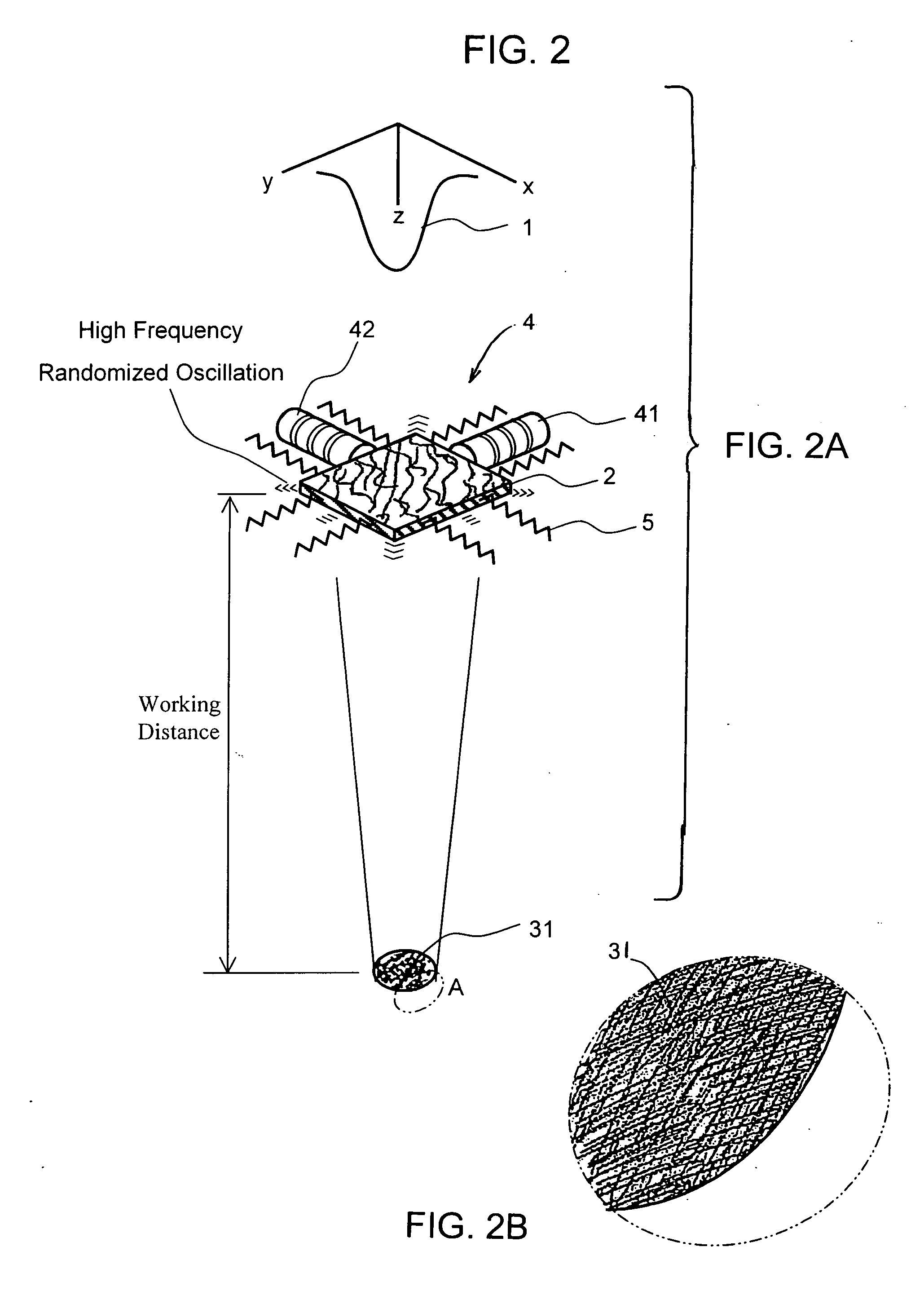
[0025]FIG. 2A shows the same CGH 2 used in FIG. 1, except that the CGH 2 is now mounted to a Speckle Reduction Optical Mount (SROM) 4, of the present invention, and the reduction in speckle noise is illustrated in further detail in FIG. 2B. As shown, Speckle Reduction Optical Mount 3 contains piezo linear actuators 41 and 42, and a number of opposed flexures or springs 5, which can randomly oscillate the CGH 2 at variable high frequencies ranging from about 1 to about 50 kHz, for example.

[0026]FIG. 3 shows a control circuit 411 for SROM 4 wherein the control circuit includes a random pulse generator 411 for generating and sending a random signal to actuator control drives 421 and 422...


PUM

PropertyMeasurementUnit
Frequencyaaaaaaaaaa
Areaaaaaaaaaaa
Frequencyaaaaaaaaaa

Abstract

An optical mount device for holographic and diffractive beam shaped image speckle reduction by active beam sampling by means of low and high frequency vibrations induced in the HOE/DOE optical mount. A holographic optical element or a diffractive optical element is placed into an optical mount which is isolated by small flexures or springs and is moved in an x-y plane at variable frequencies ranging from 1 to 50 kHz.

Description

CROSS REFERENCES TO RELATED APPLICATIONS [0001] The present Application is related to and claims benefit of U.S. Provisional Patent Application Ser. No. 60 / 673,597 filed Apr. 21, 2005 by Todd E. Lizotte, Orest Ohar and Richard Rosenberg for a HOLOGRAPHIC AND DIFFRACTIVE BEAM SHAPED IMAGE SPECKLE REDUCTION BY ACTIVE BEAM SAMPLING BY MEANS OF LOW AND HIGH FREQUENCY VIBRATIONS INDUCED IN A HOE / DOE OPTICAL MOUNT.FIELD OF THE INVENTION [0002] The present invention relates to an optical mount device for holographic and diffractive beam shaped image speckle reduction by active beam sampling by means of low and high frequency vibrations induced in the HOE / DOE optical mount. BACKGROUND OF THE INVENTION [0003] Holographic, diffractive or computer generated holographic optics used for beam shaping are typically used to shape or transform a beam with an undesirable output profile or phase, into a desirable profile or phase, such as a Gaussian laser beam profile being transformed into a Flat Top...

Claims


Application Information

Patent Timeline
IPC IPC(8): G01P3/36
CPCB23K26/073G02B5/32G03H1/32G03F7/70091G03F7/70825G02B27/48
Inventor LIZOTTE, TODD E.OHAR, ORESTROSENBERG, RICHARD
Owner HITACHI SEIKO LTD
Why Eureka
Try Eureka