
On-demand publishing system

a publishing system and publishing technology, applied in the field of information processing equipment, can solve the problems of reducing setting errors, and no system is proposed which unitarily sets the finisher and printing apparatus, so as to prevent the generation of any setting error, the effect of increasing the productivity of printing processing

Active Publication Date: 2006-10-26
CANON KK
View PDF13 Cites 53 Cited by
  • Summary
  • Abstract
  • Description
  • Claims
  • Application Information

AI Technical Summary

Benefits of technology

The present invention provides an information processing apparatus that can automatically make settings that match printing attributes, by generating post-processing setting information based on function information and identifying the printing function and post-processing function processible by a post-printing processing device. This improves productivity and prevents setting errors, and a control method therefor. Additionally, a printing system is provided that includes the information processing apparatus and a printing device connected by communication, where the information processing apparatus generates printing information and the printing device generates printing data based on the printing information. The post-processing setting information generated by the information processing apparatus is transmitted to the post-printing processing device, which simplifies the programming of the information processing apparatus and reduces errors. The invention also allows the user to prioritize the use of a post-printing processing device connected in line to the printing device, reducing labor and increasing productivity.

Problems solved by technology

In particular, no system is proposed which unitarily sets a finisher and printing apparatus by an information processing apparatus such as a computer for controlling the printing apparatus.
It imposes a burden on the operator to maintain matching between the settings of the printing apparatus and finisher, decreasing the productivity of printing processing and generating a setting error.

Method used


Image

  • On-demand publishing system
  • On-demand publishing system
  • On-demand publishing system

Examples


first embodiment

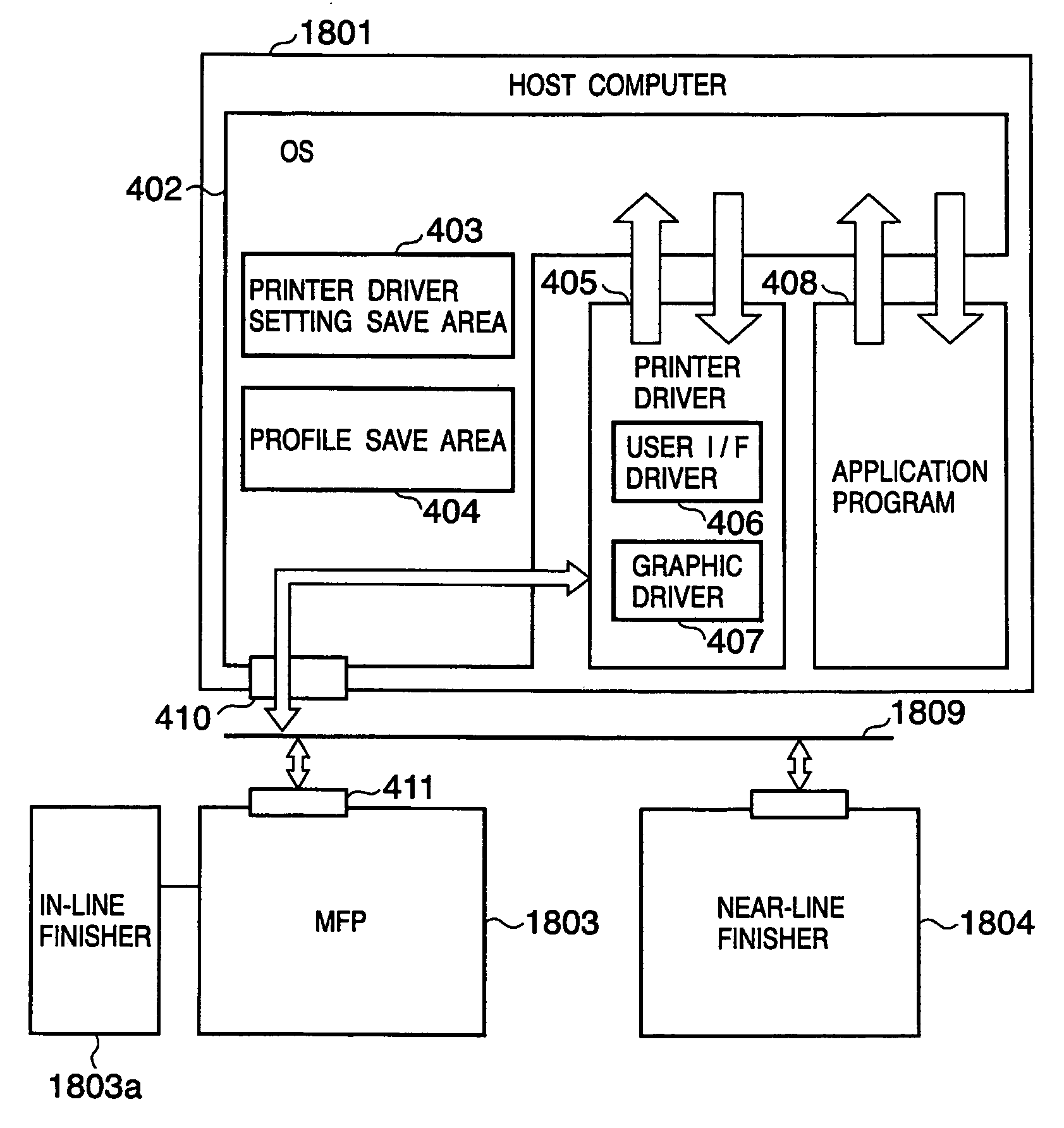
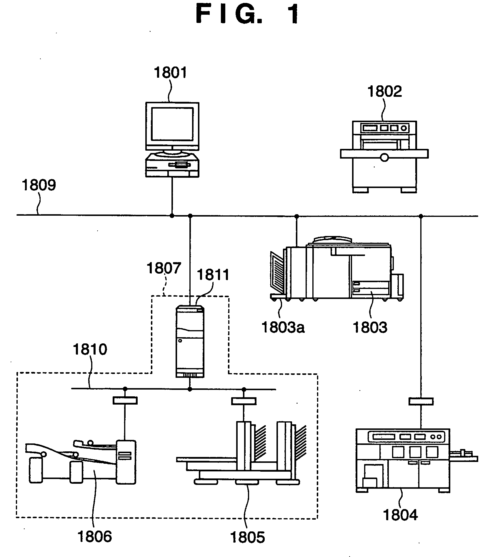
[0075]FIG. 1 is a view showing an example of a system configuration according to the present invention. A DTP (Desk Top Publishing) system in FIG. 1 comprises a client PC 1801, an image forming apparatus (printer or printing apparatus) 1803, an in-line finisher 1803a connected in line to the image forming apparatus 1803, a near-line finisher (bookbinding apparatus with a casing-in function) 1804 connected to a network 1809, an off-line finisher 1802 not connected to the network 1809, and a finisher system 1807. The finisher system 1807 can connect one or a plurality of finishers, i.e., a bookbinding apparatus 1805 with a saddle stitch function, a folding apparatus 1806, and a controller 1811 to a network 1810, and control them. A finisher connected to the network 1810 via the controller 1811 is also called a near-line finisher. Devices connected to the network can communicate with each other via the network. The printer 1803 comprises an image scanner, and is a multi-functional appa...

second embodiment

[0166] In some cases, the user can use a plurality of finishers. For example, the user can utilize an in-line finisher connected in line to a printer, a near-line finisher which is independent of the printer but is connected via a network, and an off-line finisher which is not connected even by communication. In this case, according to the first embodiment, the user is prompted to select a finisher for use on the user interface of the printer driver. The user can make settings of the selected finisher.

[0167] To the contrary, a purpose of the second embodiment is to provide an information processing apparatus which automatically selects a finisher, and allows the user to make settings without being aware of the presence of the finisher on the user interface of the printer driver.

[0168] The second embodiment will be explained with reference to FIG. 29 and following drawings. FIG. 29 is a view showing an example of a system configuration according to the present invention. As shown i...

first modification

[First Modification]

[0173] The first modification to the second embodiment will be explained. FIG. 31 shows an example of some of the contents of a finisher management table 902 (FIG. 9). This table stores information on a finisher connectable to the image forming apparatus, as shown in FIG. 10. In this modification, priority is stored in addition to the items in FIG. 10 so as to allow the user to change the priority. The flow of printing processing by the host in this modification will be described with reference to FIG. 32.

[0174] The user creates data to be printed by using an application, and calls the driver to print. In response to this, the driver is activated (S3201). If the property button in FIG. 18 is clicked in the setting window, the driver displays a detailed setting window in order to set a finisher (S3202). In order to permit the user to set finishing processing for the data to be printed, the driver further displays a detailed setting window (finishing sheet) (S3203...


PUM


Abstract

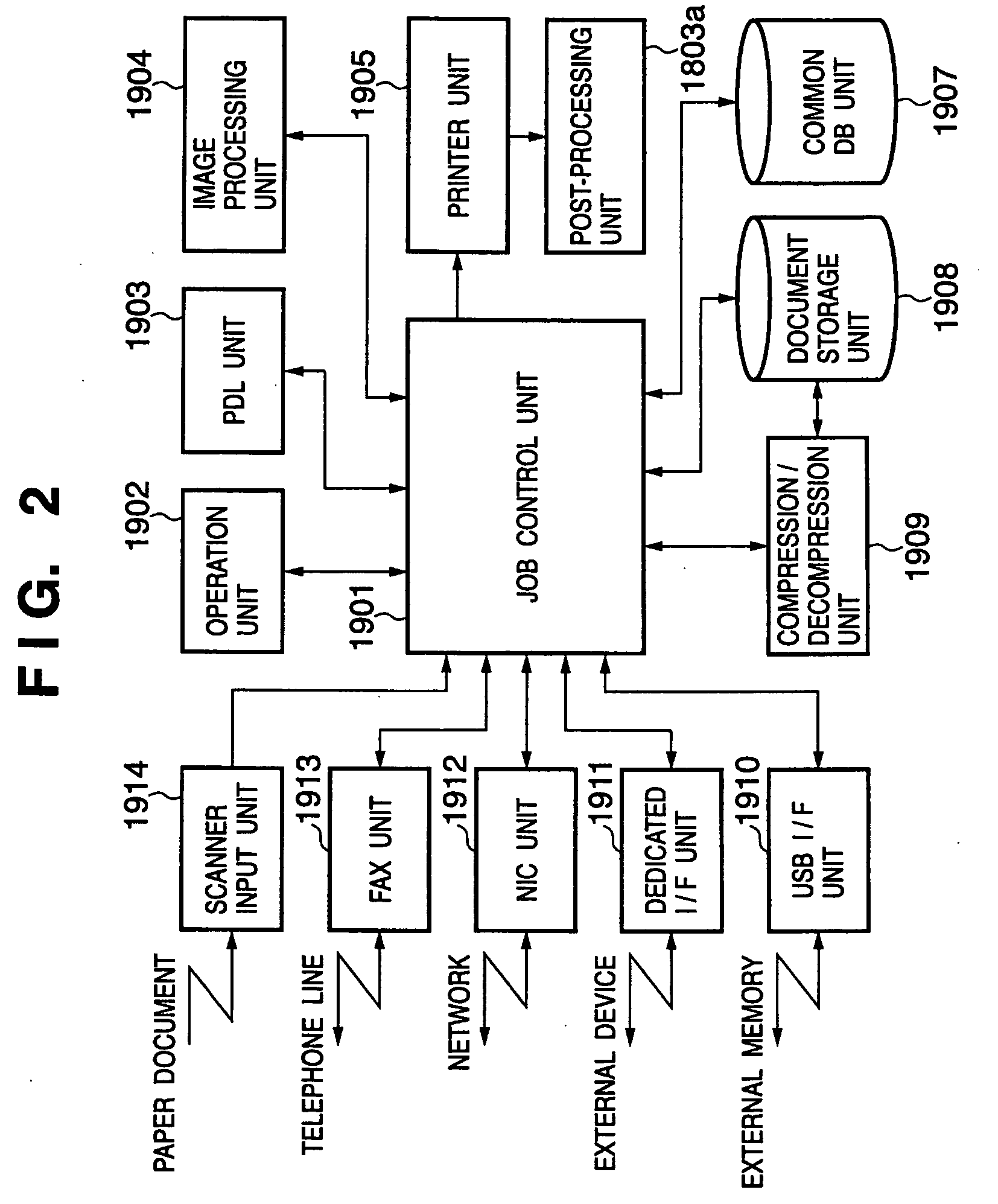
According to the present invention, an information processing apparatus comprises: a loading unit which loads function information representing a function of the post-printing processing device; an identification unit which identifies a printing function processible by the printing device and a post-processing function processible after printing by the post-printing processing device; a display control unit which displays a setting window for setting the printing function and post-processing function; a data generation unit which generates printing data to be printed by the printing device; and a setting information generation unit which generates post-processing setting information subjected to post-printing processing by the post-printing processing device, wherein the printing data is transmitted to the printing device, and the post-processing setting information is transmitted to the post-printing processing device.

Description

FIELD OF THE INVENTION [0001] The present invention relates to an information processing apparatus which outputs printing information to a printing apparatus and post-processing information to a post-processing apparatus in a printing system configured by connecting, by a network, an image forming apparatus (e.g., a digital copying machine), a post-processing apparatus (e.g., an in-line finisher, near-line finisher, or off-line finisher), and a client computer in which a printer driver for controlling the image forming apparatus is installed, and a control method therefor. BACKGROUND OF THE INVENTION [0002] Terms will be explained. A finisher means a post-printing processing apparatus, and is also called a post-press process apparatus or simply a post-processing apparatus. The finisher executes various processes such as bookbinding, cutting, stapling, punching, and collate. Some finishers have multiple functions, and some have single functions. [0003] Feature information of an appar...

Claims


Application Information

Patent Timeline
Patent Type & Authority Applications(United States)
IPC IPC(8): G06F3/12
CPCG06F3/1204G06F3/1288G06F3/1264G06F3/1208G06F3/12
Inventor AKASHI, MASAMICHISAKURA, MASAYUKIMATSUZAKI, MASANORIANNO, MAKOTO
Owner CANON KK
Learn More