Sound quality adjusting apparatus and sound quality adjusting method

a technology of sound quality and adjustment device, which is applied in the direction of transducer details, speech analysis, instruments, etc., can solve the problems of difficult flat frequency characteristics of television set speakers, harsh sound to the ear, and limited size and shape of speakers mounted on tv sets that reproduce such sound signals, so as to prevent the deterioration of the sound quality of high frequency components, the effect of easy hearing

Inactive Publication Date: 2006-10-26
PANASONIC CORP
View PDF11 Cites 10 Cited by
  • Summary
  • Abstract
  • Description
  • Claims
  • Application Information

AI Technical Summary

Benefits of technology

[0018] An object of the present invention is to provide a sound quality adjusting device capable of reducing sibilants without causing deterioration in sound quality of a high frequency component of a reproduced sound signal, and a sound quality adjusting method.

Problems solved by technology

On the other hand, speakers mounted on a television set that reproduces such sound signals are limited in size and shape due to restrictions on space caused by being incorporated into the television set and on cost.
Therefore, it is difficult for the speakers of a television set to have flat frequency characteristics in a low frequency range to a high frequency range.
Furthermore, there is a problem that because of the disturbance of frequency characteristics of a high frequency range, the pronunciation of “sa”, “shi”, “su”, “se” and “so” in words that an announcer utters is markedly emphasized, which sounds harshly to the ear.

Method used


Image

  • Sound quality adjusting apparatus and sound quality adjusting method
  • Sound quality adjusting apparatus and sound quality adjusting method
  • Sound quality adjusting apparatus and sound quality adjusting method

Examples


first embodiment

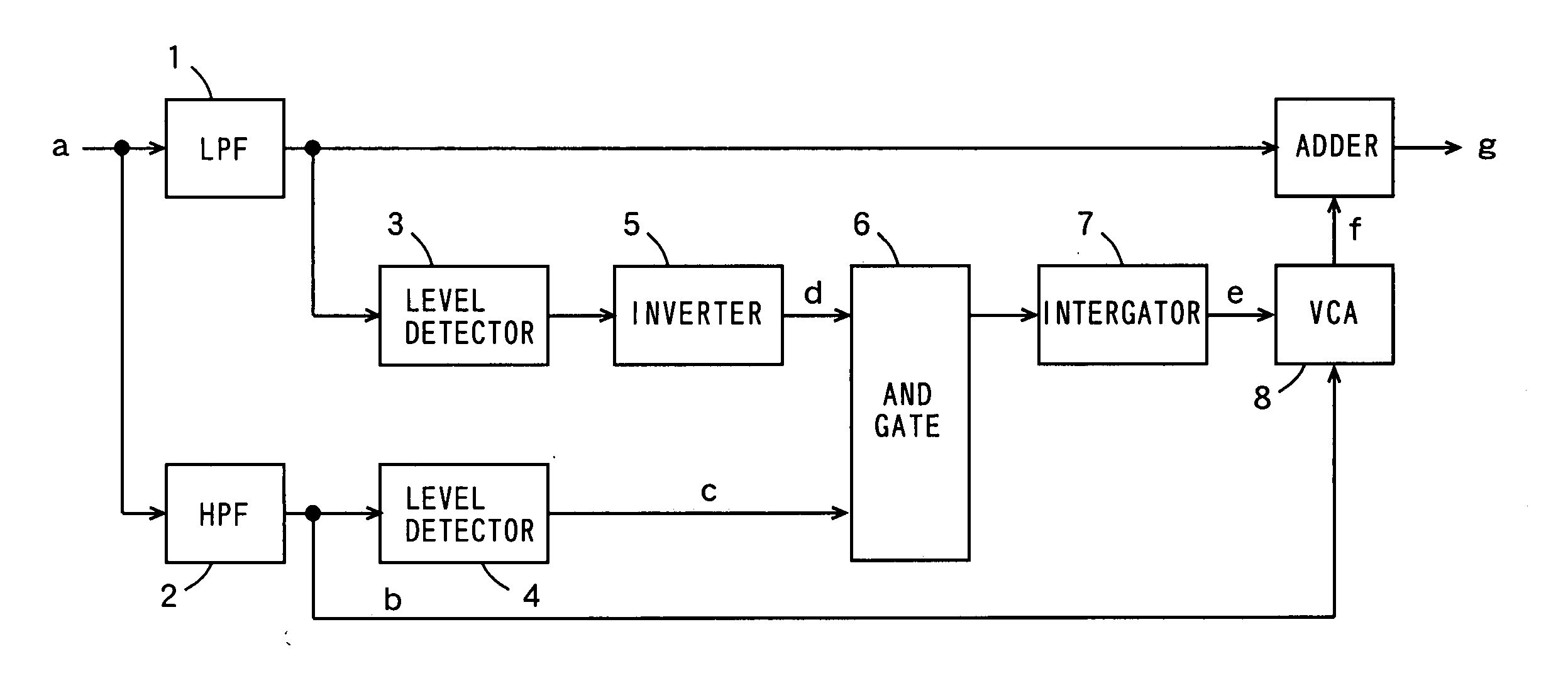
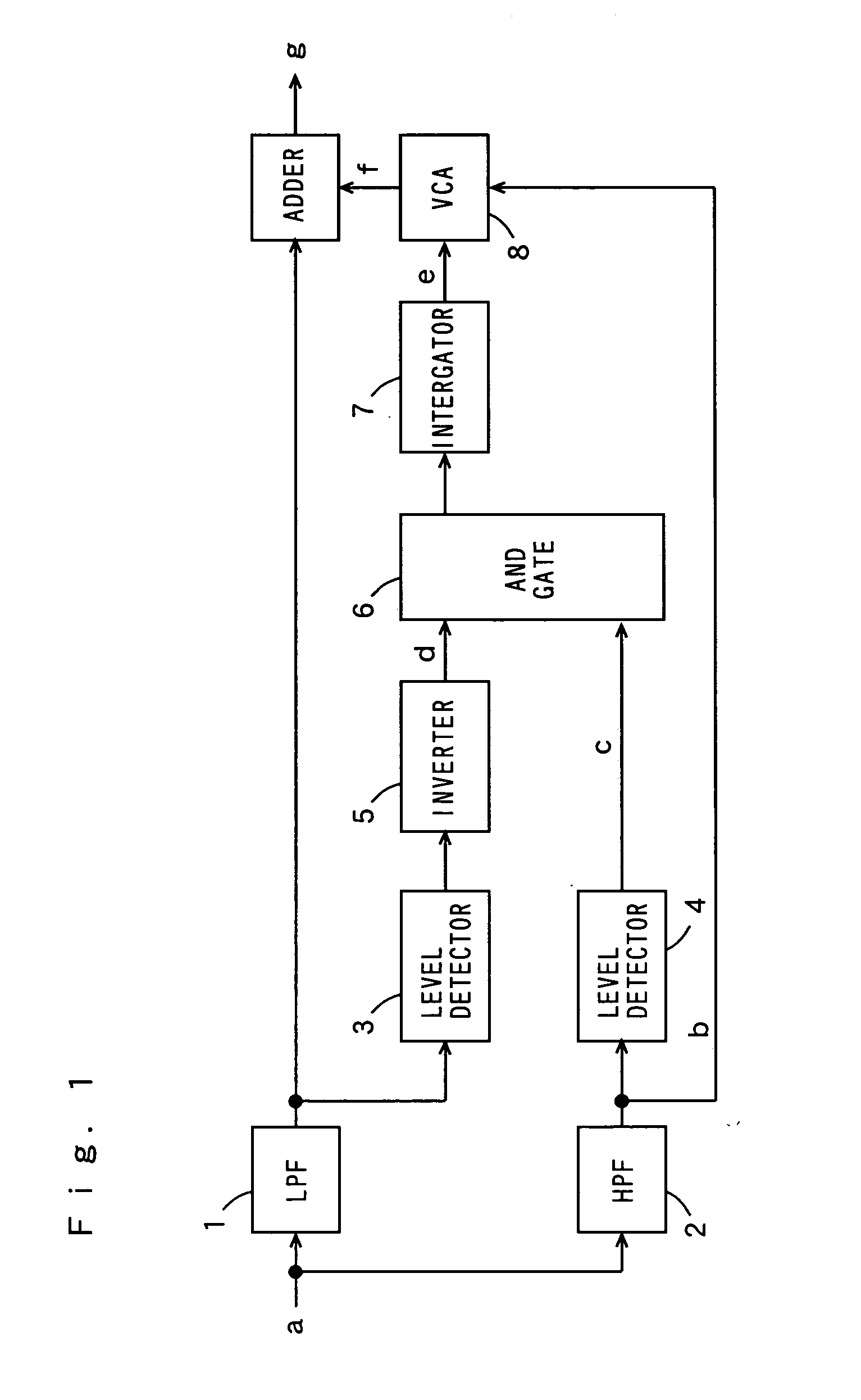
[0065]FIG. 1 is a block diagram showing a configuration of a sound quality adjusting device according to a first embodiment of the present invention.

[0066] The sound quality adjusting device of FIG. 1 includes a low pass filter (hereinafter, abbreviated to LPF), a high pass filter (hereinafter, abbreviated to HPF) 2, level detectors 3 and 4, an inverter 5, an AND gate 6, an integrator 7, a volume control amplifier (hereinafter, abbreviated to VCA) 8, and an adder 9.

[0067] The LPF 1 extracts a medium and low frequency component by passing the medium and low frequency component of not higher than 5 kHz of an inputted sound signal. The HPF 2 extracts a high and low frequency component by passing a high frequency component of not higher than 5 kHz of the inputted sound signal.

[0068] The level detector 3 detects the level of an output signal of the LPF 1 and when the detected level is equal to or higher than a predetermined value, a signal of H level (high level) is outputted, while w...

second embodiment

[0099]FIG. 5 is a block diagram showing a configuration of a sound quality adjusting device according to a second embodiment of the present invention.

[0100] The sound quality adjusting device of FIG. 5 includes the LPF 1, the HPF 2, the level detector 3, the inverter 5, the integrator 7, the VCA 8 and the adder 9.

[0101] The LPF 1 extracts a medium and low frequency component by passing a medium and low frequency component of not higher than 5 kHz of an inputted sound signal. The HPF 2 extracts a high frequency component by passing a high frequency component of not lower than 5 kHz of the inputted sound signal. The level detector 3 detects the level of an output signal of the LPF 1 and when the detected level is higher than a predetermined value, a signal of H level (high level) is outputted, while when the detected level is lower than the predetermined value, a signal of the L level (low level) is outputted.

[0102] The inverter 5 inverts the level of an output signal of the level ...

example

[0125] In the present example, the sound quality of the uttered word was adjusted using the sound quality adjusting device of FIG. 1. FIG. 7 is a diagram showing a measurement result of the spectrum of the uttered word. FIG. 8 is a diagram showing a measurement result of the spectrum of the voice sound whose sound quality has been adjusted. Here, the high frequency component of 5 kHz or higher was attenuated by 10 dB by the sound quality adjusting device of FIG. 1. The uttered word is “shashin”.

[0126] The abscissa of the FIGS. 7 and 8 indicates frequency and the ordinate thereof indicates amplitude. When comparing the spectrum of FIG. 8 with the spectrum of FIG. 7, the spectrum of FIG. 8 shows that the high frequency component of 5 kHz or higher in the spectrum of FIG. 7 has been attenuated. Thereby, the sibilants that sound harshly to the ear are attenuated, so that the sound easy to hear is reproduced.

Other Modifications

[0127] While in the above-described first embodiment, the ...


PUM


Abstract

An LPF extracts a medium and low frequency component of an inputted sound signal. An HPF extracts a high and low frequency component in the inputted sound signal. One of the two level detectors determines whether the medium and low frequency component exists by detecting the level of an output signal of the LPF. The other level detector determines whether the high frequency component exists by detecting the level of an output signal of the HPF. An inverter inverts the level of an output signal of the one level detector. An AND gate operates an AND of an output signal of the inverter and an output signal of the other level detector. An integrator integrates an output signal of the AND gate. A VCA determines that the sound signal is a sibilant when the medium and low frequency component does not exist and when the high frequency component exists, and attenuates the level of the output signal of the HPF, while the VCA determines that the sound signal is a normal speech sound when the medium and low frequency component exist and outputs the output signal of the HPF without modification. An adder synthesizes the output signal of the LPF and the output signal of the VCA by addition.

Description

TECHNICAL FIELD [0001] The present invention relates to a sound quality adjusting device and a sound quality adjusting method that adjusts the sound quality of a reproduced sound. BACKGROUND ART [0002] With the start of BS (satellite) broadcasting, sound signals in a current television system have come to be transmitted in a digital signal format, having a wide frequency band from a low frequency range to a high frequency range, flat frequency characteristics, and a high quality with less noise. On the other hand, speakers mounted on a television set that reproduces such sound signals are limited in size and shape due to restrictions on space caused by being incorporated into the television set and on cost. Therefore, it is difficult for the speakers of a television set to have flat frequency characteristics in a low frequency range to a high frequency range. [0003] Consequently, there are proposed various methods for improving the sound quality at the time of reproduction (JP 2002-...

Claims


Application Information

Patent Timeline
Patent Type & Authority Applications(United States)
IPC IPC(8): H03G5/00G10L21/02H03G5/16
CPCG10L21/0364H03G5/165G10L21/02
Inventor ODA, MIKIO
Owner PANASONIC CORP
Why Eureka
Try Eureka