Continuous balloon structures - 2

a balloon and continuous technology, applied in the field of balloons, can solve the problems of relatively few systems specially designed and manufactured for these purposes, the film commonly used for balloons, is not strong, and easily penetrates, so as to prevent the deflation of all inflatable chambers, save time and material

Inactive Publication Date: 2006-10-26
ROUSE GRAHAM MANLY
View PDF7 Cites 14 Cited by
  • Summary
  • Abstract
  • Description
  • Claims
  • Application Information

AI Technical Summary

Benefits of technology

[0039] The second method is to include a manifold in the continuous balloon structure that incorporates self-sealing valves where the manifold has fluid communication with each inflatable chamber or group of chambers. All chambers (or groups of chambers) connected to the manifold could be inflated at once, but the self-sealing valves would keep one chamber (or group of chambers) from leaking just because of a leak in another, connected chamber (or group of chambers). This can be achieved by the same general process described earlier in which a plurality of die applications are made to a plurality of layers of film in such a way as to establish fluid communication between chambers created by the die applications. A manifold was suggested and illustrated in the original form of this application. We are simply specifying the inclusion of separate self-sealing (check valves) for each inflatable chamber as a method of preventing the deflation of all inflatable chambers in the system when one develops a leak. This method does give up the ease of deflating all chambers at once when desired.
[0040] The third method is to manufacture inflatable chambers in a connected series through a plurality of die applications to a plurality of layers of film but without fluid communication between the chambers. Such a continuous balloon structure can save time and material otherwise required for assembly of a balloon display. It can also assure the relative placement of inflated chambers within the display. It does give up the advantage of inflating all the chambers at once and the advantage of deflating all chambers at once when desired.

Problems solved by technology

There are, however, relatively few systems especially designed and manufactured for these purposes.
One exception, however, is the use of paper clips or other wire hooks poked through the uninflated stem of the latex balloon, because films commonly used for balloons, although quite strong, tear easily once penetrated.
A second exception is pinching and twisting a film balloon across an inflated chamber, because the relatively inelastic nature of films often makes such a procedure impractical.
Under current standard manufacturing methods for film balloons, a single die may produce multiple identical balloons either by repeated application or by one application of a complex die, however, the balloons thus created are not in fluid communication.
In order to save them for reuse, however, each balloon manufactured under current methods must be unsealed, deflated and packed for storage independently.
This can save significant time in deflating and storing the display.
The biggest disadvantage of such a system of inflatable chambers is the possibility that a leak may occur in one of the series of inflated chambers.
A leak in one of the chambers could lead to the premature deflation of all of the chambers in the series.

Method used


Image

  • Continuous balloon structures - 2
  • Continuous balloon structures - 2
  • Continuous balloon structures - 2

Examples


Embodiment Construction

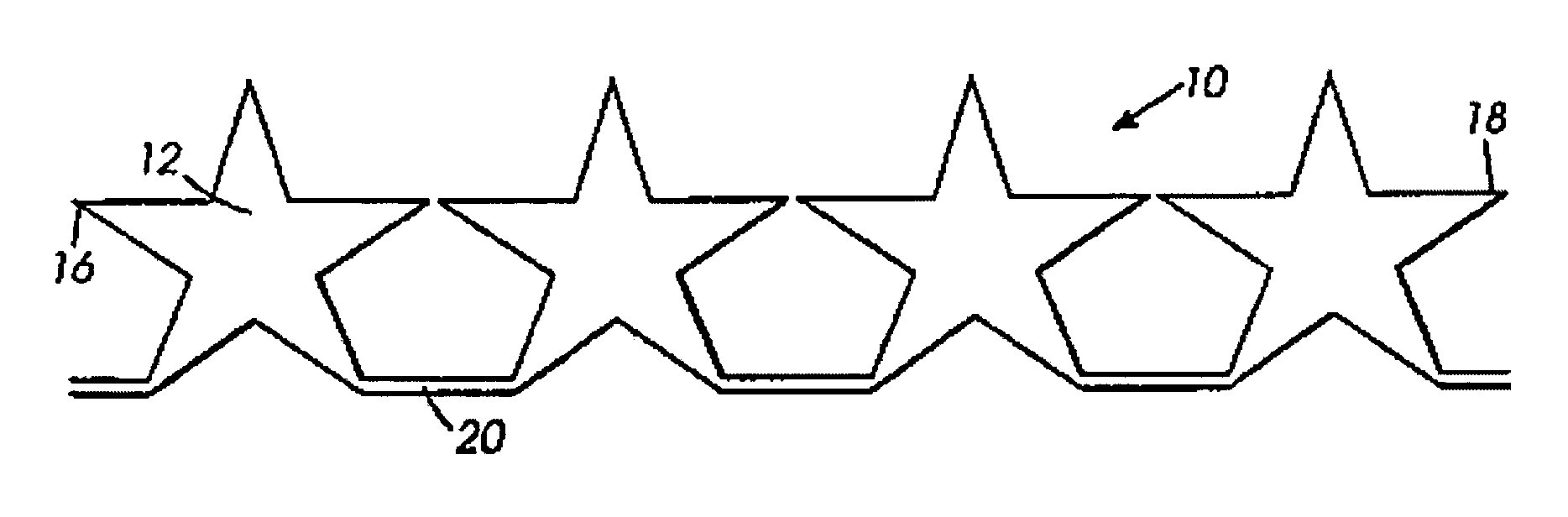
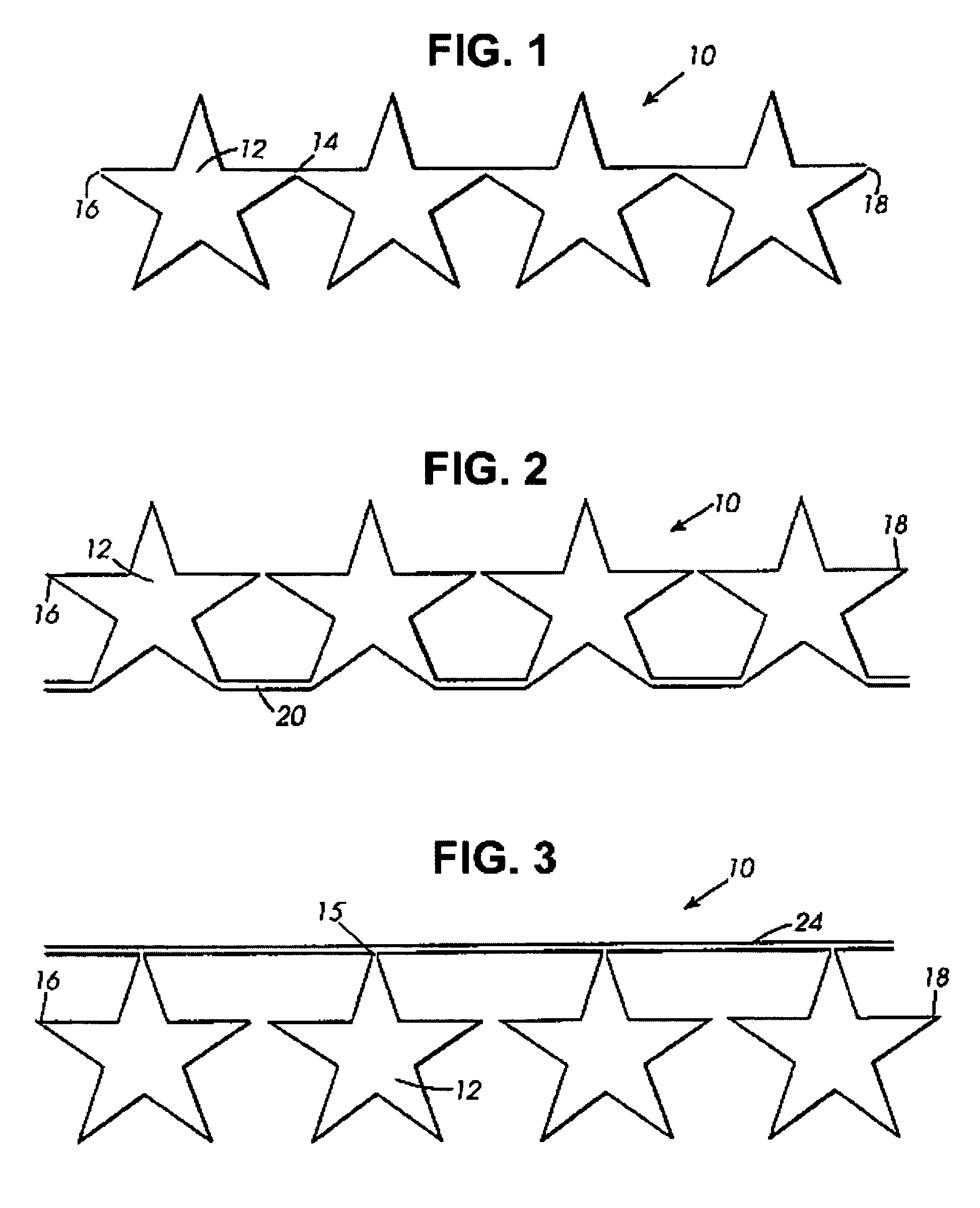
[0151] The present claims address a continuous balloon structure and a method for making continuous balloon structures. This structure would most often be inflated with gas, sealed and used as a balloon display with decorative, informative and / or structural value. It may, however, be used without the chambers being filled or with chambers filled with other fluids. The structure might also be used as a conduit, carrier or wrap for fluids, particles, objects, light, sound, electricity, electronic impulses, etc.

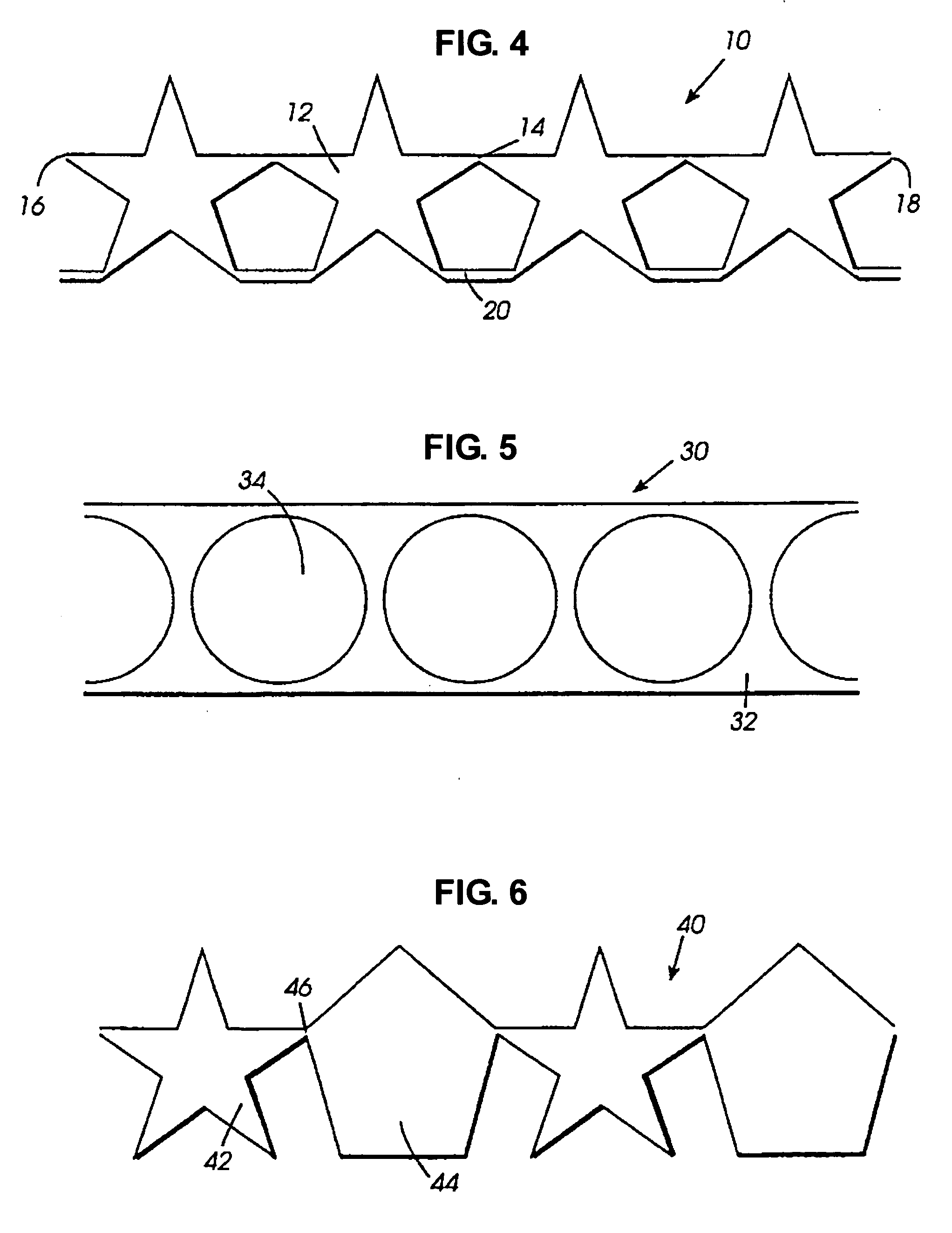
[0152] The continuous balloon structure is a plurality of connected inflatable chambers that are formed from a plurality of layers of film by a plurality of die applications. Die applications create sets of seals between layers of film. The area encompassed by all seals is greater than the area encompassed by any single set of seals.

[0153] The continuous balloon structure can be in the form of a linear, arcuate or circular sequence of inflatable chambers, or a variety of two a...


PUM


Abstract

A structural, informative and/or decorative balloon display is comprised of a plurality of connected, inflatable chambers formed by a plurality of die applications to a plurality of layers of film. The largest die application produces a set of seals that encompasses an area smaller than the area encompassed by all such sets of seals. In one preferred embodiment connected chambers have and maintain fluid communication. In another preferred embodiment, connected, inflatable chambers have no fluid communication but have a beginning and an end. In other preferred embodiments fluid communication is terminated after inflation. Other embodiments take advantage of variations of numbers of layers, configurations of layers, and treatment of surfaces to create special balloon forms.

Description

CROSS REFERENCE TO RELATED APPLICATIONS [0001] This application is a continuation in part of pending application Ser. No. 10 / 326,888 by this inventor titled “Rouse Display Systems” (RDS) filed 12 / 19 / 2002. The entire content of application Ser. No. 10 / 326,888 is hereby included by reference as part of this application. [0002] Application Ser. No. 10 / 326,888 claimed benefit and priority date of provisional application No. 60 / 341,928 titled “Balloon Display Systems” (BDS) filed Dec. 19, 2001. The current application also claims benefit and priority date of provisional application No. 60 / 341,928 titled “Balloon Display Systems” (BDS) filed Dec. 19, 2001 [0003] Application Ser. No. 10 / 326,888 is, in turn, a continuation in part of two applications by this inventor. They are application Ser. No. 10 / 002,963 titled “Continuous Balloon Structures” (CBS) filed Dec. 05, 2001 and application Ser. No. 09 / 542,674 titled “Advanced Aperture Framework Balloon Display” (AAD) filed Apr. 01, 2000. The ...

Claims


Application Information

Patent Timeline
Patent Type & Authority Applications(United States)
IPC IPC(8): A63H27/10
CPCA63H27/10A63H2027/1075A63H2027/1025
Inventor ROUSE, GRAHAM MANLY
Owner ROUSE GRAHAM MANLY
Why Eureka
Try Eureka