Ultrasound guided tissue measurement system

a tissue measurement and ultrasound technology, applied in the field of ultrasound guided tissue measurement system, can solve the problems of inability to accurately determine tissue state, inability to use the working channel described, and inability to achieve the effect of stiff multi-sensor needle probes

Inactive Publication Date: 2006-10-26
BIOTELLIGENT
View PDF10 Cites 75 Cited by
  • Summary
  • Abstract
  • Description
  • Claims
  • Application Information

AI Technical Summary

Benefits of technology

[0016] In another embodiment of the system the probe guide is motorized to drive the probe into the tiss

Problems solved by technology

Ultrasound imaging alone now provides accurate guidance but lacks the contrast to accurately determine tissu

Method used


Image

  • Ultrasound guided tissue measurement system
  • Ultrasound guided tissue measurement system
  • Ultrasound guided tissue measurement system

Examples


Embodiment Construction

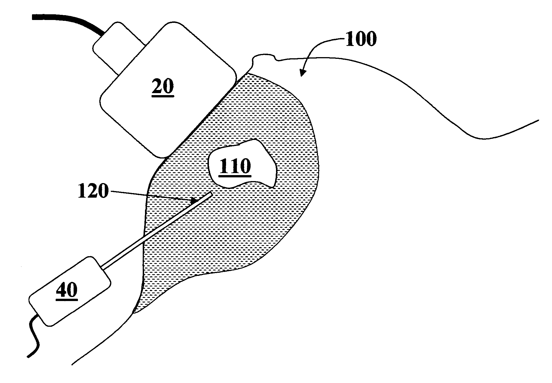
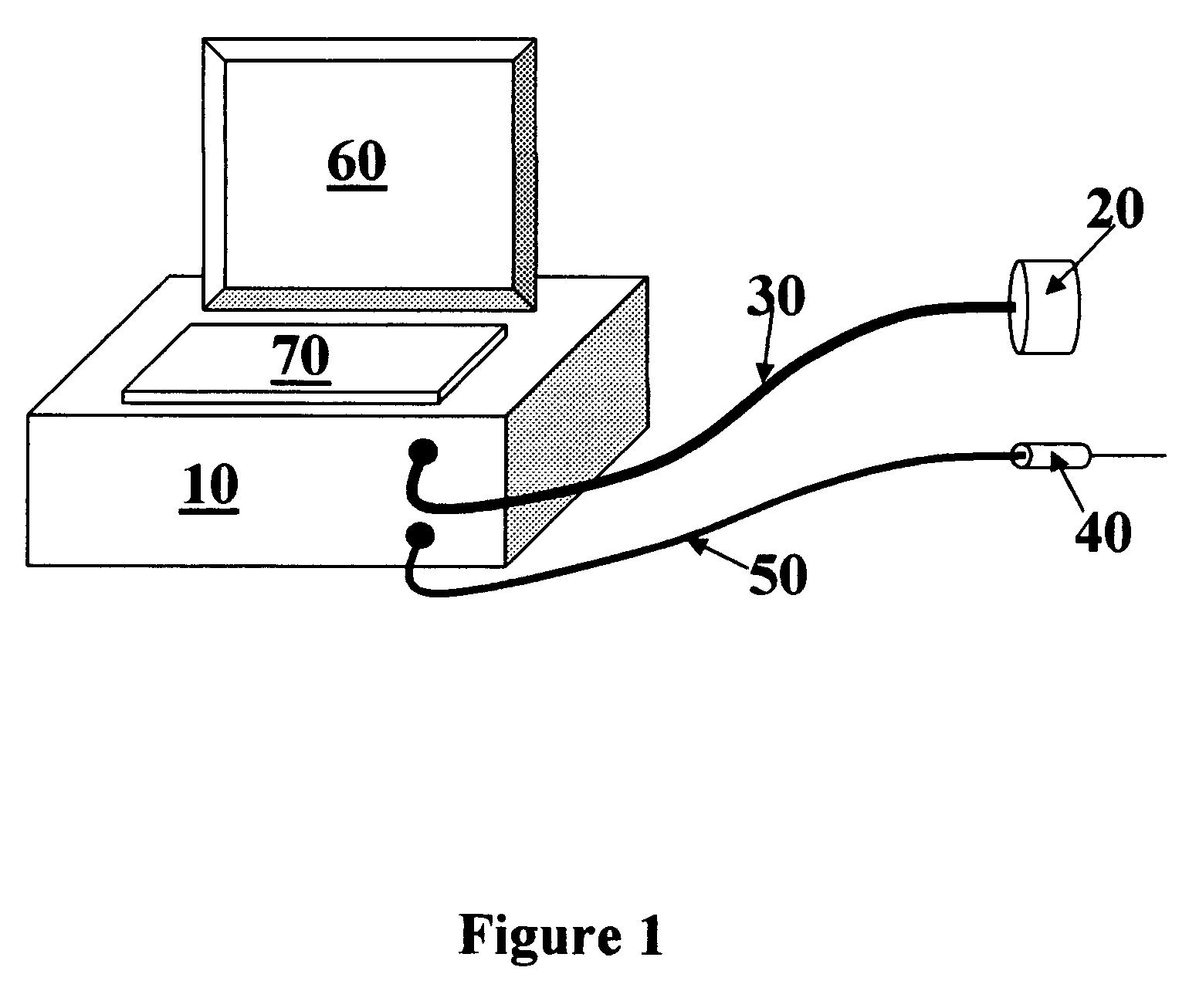
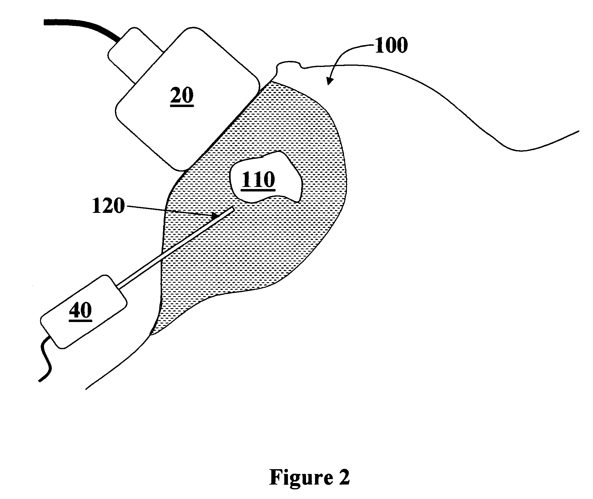
[0022] The present invention provides a system that can be used by physicians to accurately position a tissue measurement probe and provide a diagnosis. FIG. 1 shows the major components of the measurement system. A control electronics module 10 connects to an ultrasound imaging transducer 20 through a cable 30. A tissue measuring probe 40 connects to the control module 10 through cable 50. In normal use the control electronics 10 collect data from the ultrasound transducer 20 and tissue probe 40 and processes the data for display on monitor 60. A user interface 70 is used by the user to control data acquisition, data display and analysis.

[0023] The ultrasound imaging transducer 20 can be mechanically scanned or a phased array design (see, e.g., “The Physics of Medical Imaging” Ed. Steve Webb (1988), incorporated herein by reference and “Ultrasound in Medicine” Ed. F. A. Duck, A. C. Baker, H. C. Starritt (1997), incorporated herein by reference). Although a two dimensional imaging ...


PUM


Abstract

A tissue guidance system integrates an ultrasound imaging device with a tissue diagnostic probe. Ultrasound imaging is used to guide the tissue probe to the target area. Measurements made by the probe can then be analyzed to determine tissue type or state (e.g., malignant or benign).

Description

[0001] This application claims priority to U.S. Provisional Patent Application Ser. No. 60 / 674,135, titled: “Ultrasound Guided Tissue Measurement System”, filed Apr. 21, 2005, incorporated herein by reference. [0002] This application is a continuation-in-part of U.S. patent application Ser. No. 11 / 375,873, filed Mar. 13, 2006, titled “Optical Biopsy System With Single Use Needle Probe”, incorporated herein by reference. This application is a continuation-in-part of U.S. patent application Ser. No. 10 / 803,574 filed Mar. 17, 2004, incorporated herein by reference. This application claims priority to U.S. Provisional Patent Application Ser. No. 60 / 455,536, filed Mar. 17, 2003, incorporated herein by reference. This application claims priority to U.S. Provisional Patent Application Ser. No. 60 / 760,196, filed Jan. 18, 2006, incorporated herein by reference.BACKGROUND OF THE INVENTION [0003] 1. Field of the Invention [0004] The invention relates to a tissue diagnostic system for determini...

Claims


Application Information

Patent Timeline
IPC IPC(8): A61B8/00
CPCA61B5/0084A61B5/0091A61B5/4312A61B2017/3413A61B8/0841A61B8/4218A61B8/0833
Inventor DA SILVA, LUIZ B.CHASE, CHARLES L.
Owner BIOTELLIGENT
Why Eureka
Try Eureka