Method for manufacturing a stator winding

a technology of stator coil and manufacturing method, which is applied in the direction of magnetic bodies, instruments, and apparatus for web record carriers, etc., can solve the problems of inability to support the intermediate parts between the top end and the bottom end, unstable bent shapes, and inability to bend straight parts in a way that is easy to deform, and achieves easy and secure folding and stacking of windings. , the effect of easy winding and high density

Active Publication Date: 2012-11-06
DENSO CORP
View PDF17 Cites 1 Cited by
  • Summary
  • Abstract
  • Description
  • Claims
  • Application Information

AI Technical Summary

Benefits of technology

[0010]The present invention was made in order to solve an aforementioned problem, and has an object to provide a manufacturing method and its manufacturing apparatus for a stator winding of a rotary electric machine, which are capable of reducing size of the coil end part and improving the space factor in the slot.
[0012]Thereby, offset shapes of the conductor are formed by the forming step before, then, after that, a winding step is performed. As a result, it is possible to keep an exact shape of the coil end part.
[0014]As a result, it is possible to perform expanding step in a measure for expanding pitch of the slot conductors by rotating the coil end parts on the winding that is folded and stacked. Therefore, it is possible to avoid applying deformation in opposite directions by pins. It is possible to avoid forming unnecessary deformations on a slot conductor part and a coil end part. As a result, it is possible to satisfy the linearity and parallelism of the slot conductor part and the accuracy of shape of the coil end part. Therefore, it is possible to improve the space factor of the winding and to form the coil end parts in a uniformly arrayed manner and in a small size.
[0016]According to the embodiment, folding and stacking of the winding in the winding step becomes easy. As a result, it is possible to wind the winding with high density. Further, in the expanding step, the turning part of the winding folded and stacked can be easily rotated, since an assist of a restoring force caused by the twisted shape is also applied. As a result, in a winding forming stage, the twisted shape is undone to a shape with small amount of twist. For example, it is possible to avoid damaging easiness of assembling process, even in a case where conductors with a rectangular shaped cross section are accommodated with less gaps in quest of a high space factor. Thus, a small size coil end parts can be formed without making manufacturing process be difficult. In addition, it is possible to manufacture with low cost, since equipment necessary for the expanding step can be simplified and number of processing is decreased.
[0018]Thereby, the winding can be performed by easily applying twisted shapes to the inclined parts and the slot conductor part of the winding. It is possible to perform folding and stacking of the winding easily and securely, and to wind the winding with high density. In addition, it is possible to manufacture with low cost, since equipment necessary for the expanding step can be simplified and number of processing is decreased.

Problems solved by technology

However, in the shifting step of the patent document 1, intermediate parts between a top end and a bottom end are not supported.
As a result, there is the possibility that the bent shapes become unstable because of wide variation of material strength, externally applied tension, orientation, and deforming amount, which are caused depending on turning parts.
As a result, the straight part may get an inadvertent deformation, and may not be provided with a necessary level of the linearity and parallelism.
Further, there is a possibility of trouble on process which includes the shifting step and succeeding steps.
In addition, there is a problem that a projecting length is too long and a size of a coil end is hardly reduced, since the turning part uses a V shaped bent structure or a loop shaped twisted structure.

Method used


Image

  • Method for manufacturing a stator winding
  • Method for manufacturing a stator winding
  • Method for manufacturing a stator winding

Examples


Embodiment Construction

[0076]Hereinafter, it is explained a first embodiment where the present invention is applied to a stator winding for an alternating current generator for a vehicle, a method for manufacturing the same, and an apparatus for manufacturing the same.

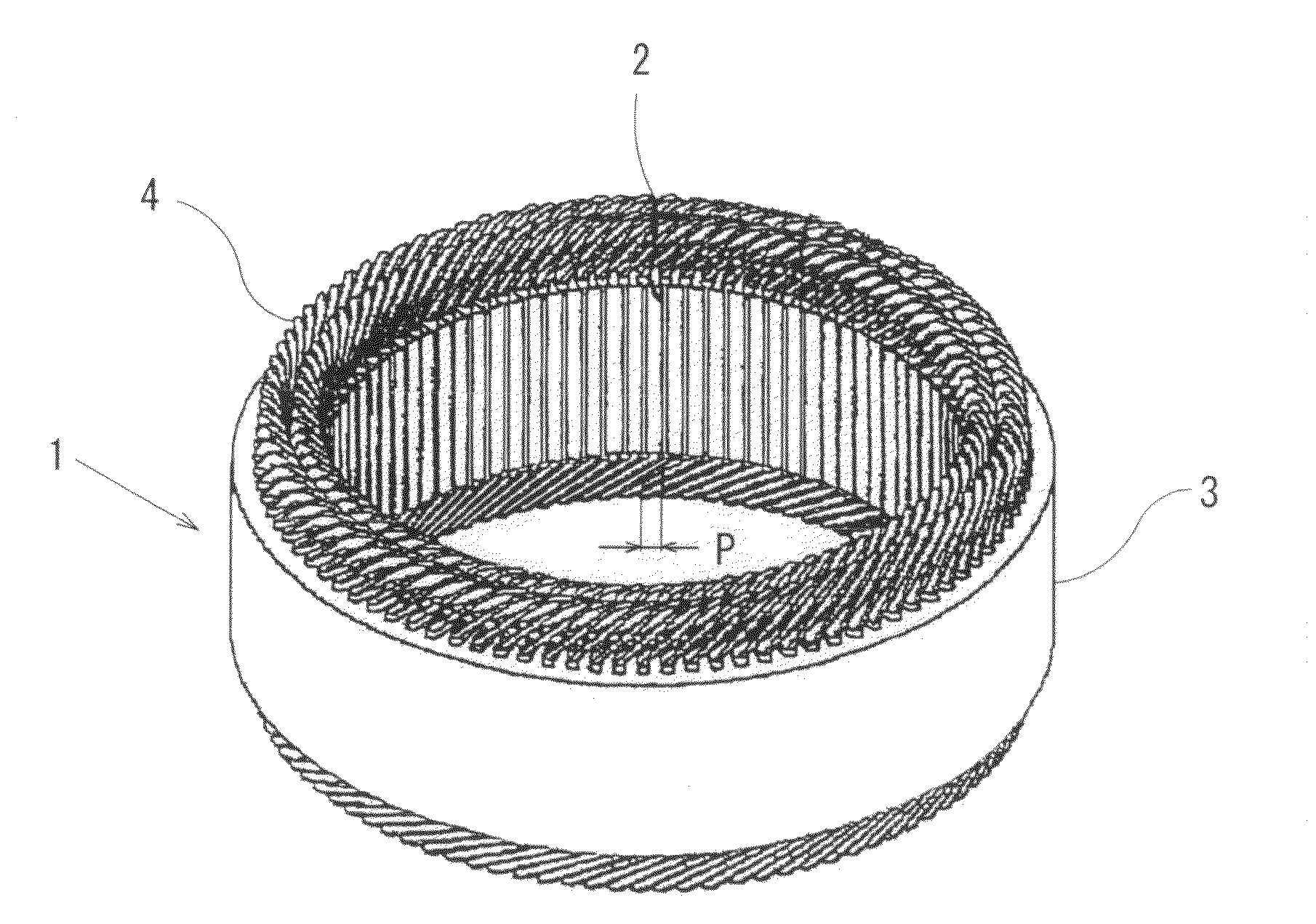
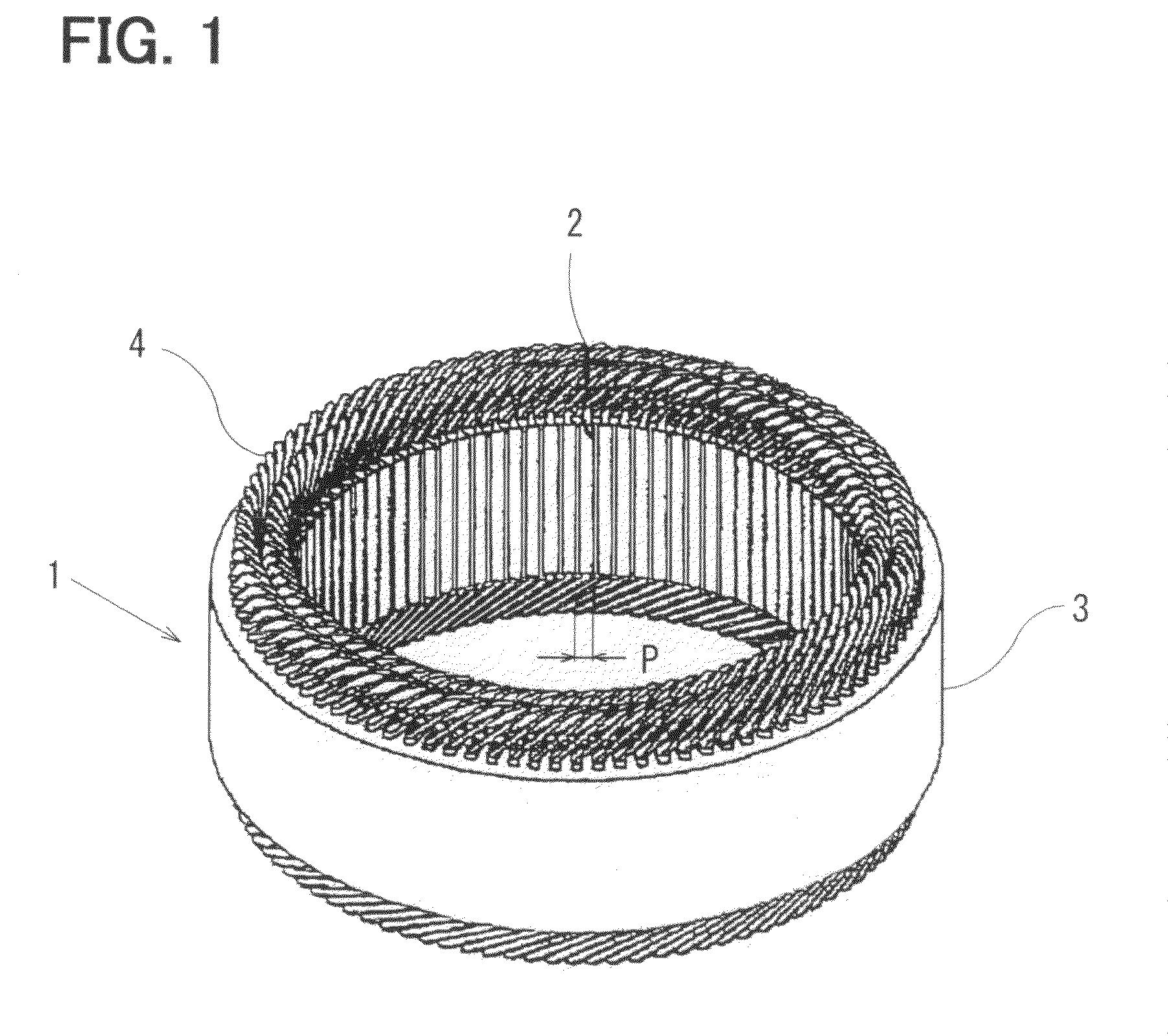
[0077]The alternating current generator for a vehicle is explained with reference to FIG. 1 to FIG. 3. The alternating current generator for a vehicle has a stator 1 and frames, not shown. The stator 1 is supported in a clamped fashion between the frames. A rotor is provided as a field and is supported in a rotatable manner. The stator 1 accommodates the rotor therein. The rotor is rotated by an internal combustion engine (engine) mounted on the vehicle. The stator 1 acts as an armature for generating a power output.

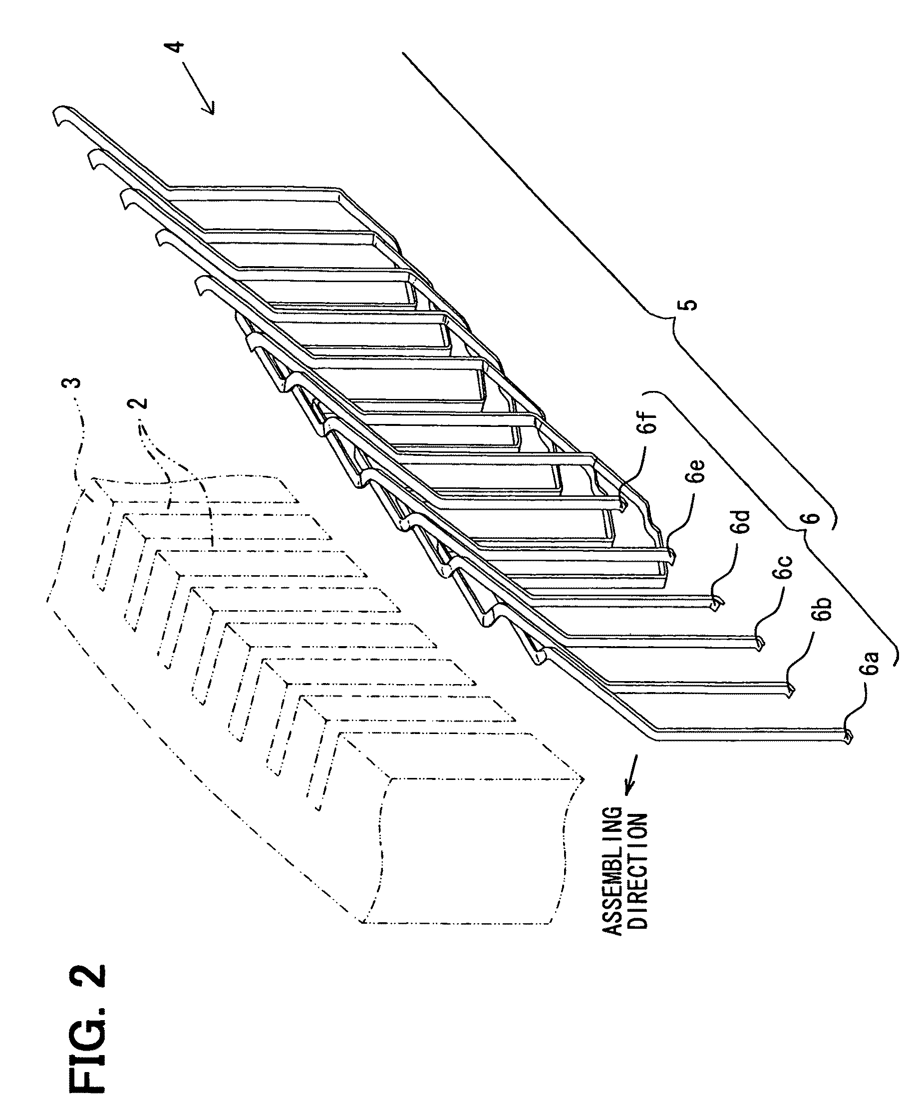
[0078]In FIG. 1, the stator 1 includes a stator core 3 and a stator winding 4. The stator core 3 is formed in a cylindrical shape where a plurality of axially extending slots 2 are formed with predetermined slot pitch P in a circ...


PUM

PropertyMeasurementUnit
twisting angleaaaaaaaaaa
shapeaaaaaaaaaa
twisting rotation forceaaaaaaaaaa

Abstract

A stator winding is manufactured by a forming step, a winding step, and a expanding step. In the forming step, an S-shaped offset shape is formed on a conductor part corresponding to a coil end part. Thereby, in a coil end part, it is possible to provide an expected shape stably at the coil end part. The conductor is wound around a bobbin in the winding step. In the winding step, a twisted shape is given to the conductor parts to be the inclined part of the coil end and the conductor part to be accommodated in a slot. In the expanding step, a preform product removed from the bobbin is expanded into a shape of the stator winding.

Description

CROSS REFERENCE TO RELATED APPLICATION[0001]This application is based on Japanese Patent Application No. 2008-253204 filed on Sep. 30, 2008, the contents of which are incorporated herein by reference in its entirety.FIELD OF THE INVENTION[0002]The present invention relates to a method for manufacturing and an apparatus for manufacturing a stator coil of a rotary electric machine, such as an alternating current generator for a vehicle.BACKGROUND OF THE INVENTION[0003]In order to provide a small and high power rotary electric machine, it is necessary to increase the space factor of a stator winding within a slot of an stator core, and to form a coil end part, i.e., a jumper part of the stator winding at an outside of the slot, in a uniformly arrayed, in a small size, and in a high density manner.[0004]A segment connecting type winding manufacturing method is known as one of the manufacturing method of and manufacturing machine for the stator windings. In this method, a plurality of U-...

Claims


Application Information

Patent Timeline
Patent Type & Authority Patents(United States)
IPC IPC(8): H01F7/06
CPCH02K15/0478Y10T29/49009Y10T29/49069Y10T29/49073Y10T29/49066Y10T29/49062Y10T29/49071
Inventor TOKIZAWA, TAKASHI
Owner DENSO CORP
Why Eureka
Try Eureka