
Methods and apparatus of downhole fluid analysis

a technology of fluid analysis and downhole, applied in the field of downhole fluid analysis, can solve the problems of frequent change of sample pressure and temperature, damage or spoilage, and damage to samples, and achieve the effect of less tim

Active Publication Date: 2006-11-02
SCHLUMBERGER TECH CORP
View PDF53 Cites 106 Cited by
  • Summary
  • Abstract
  • Description
  • Claims
  • Application Information

AI Technical Summary

Benefits of technology

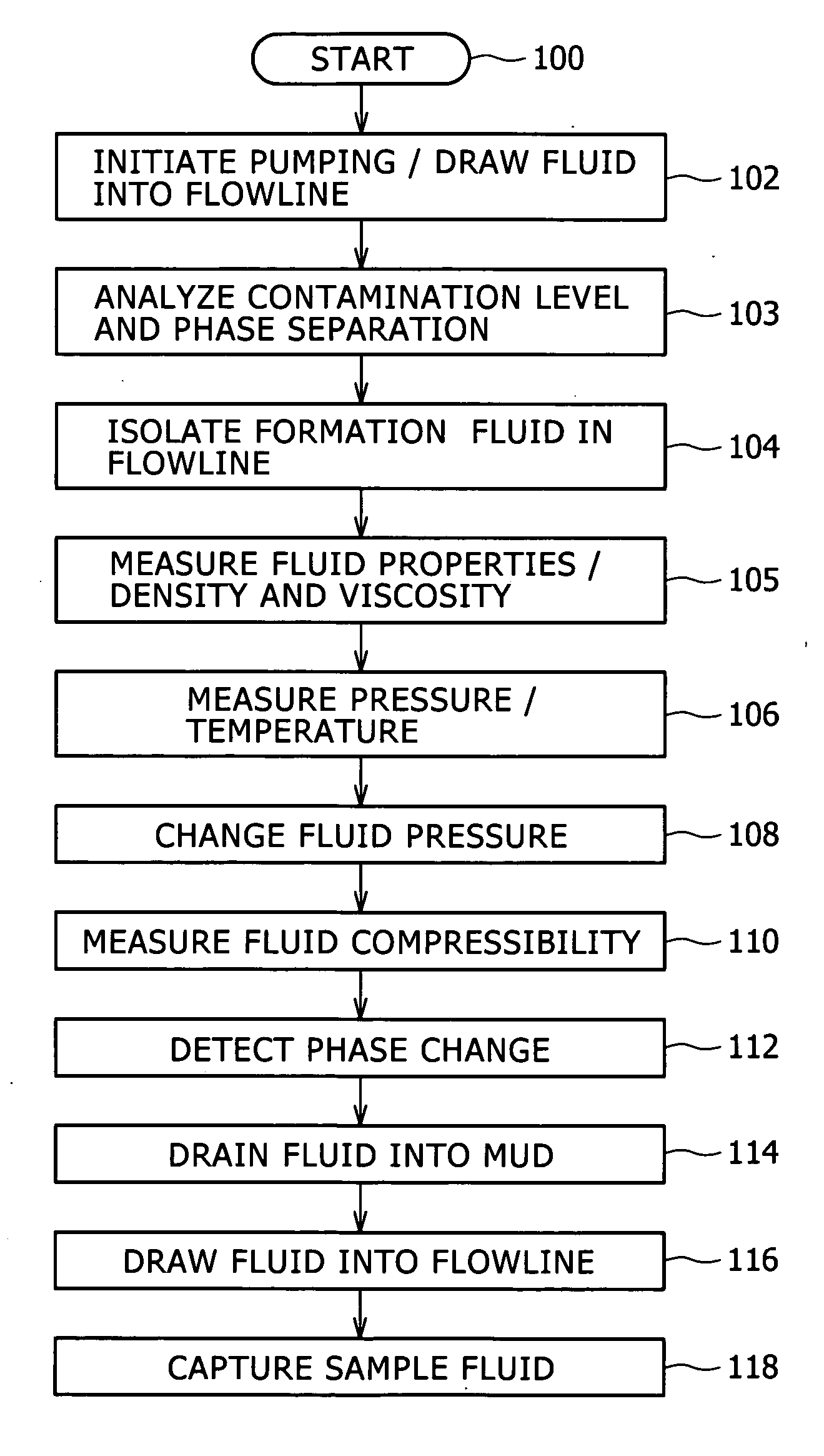
[0015] Advantageously, the PVCU is suitable for downhole applications and since the flowline and / or PVCU of the downhole tool are used to isolate formation fluids, undesirable formation fluids can easily be drained and replaced with formation fluids that are suitable for downhole characterization. Another advantageous result obtained by isolating formation fluids according to the present invention is that downhole pressure-volume-temperature (PVT) analysis of the fluids may be performed at or near downhole conditions utilizing the PVCU of the present invention.
[0019] Applicants discovered that fluid characterization performed on fluids that are isolated from a formation or borehole so as to be in relatively stable, static state tends to be more accurate in comparison with downhole analysis of fluids that are in an active flowing state while being characterized.
[0020] Applicants recognized that a fluid sample isolated in a tool flowline, as compared with a fluid sample captured in a sampling chamber of a downhole tool, has advantageous benefits since the isolated fluid may be checked for quality and be substituted with another, better quality isolated fluid if the quality of the initial fluid were found to be unsuitable for fluid characterization. In this, it is possible to flush a flowline of a fluid analysis module and extract fresh formation fluid for analysis while the tool is downhole whereas conventional sampling chambers and containers may not have means for draining sampled fluid and acquiring another sample of formation fluids while the tool is situated downhole.
[0021] Applicants further recognized that having an isolated fluid downhole under conditions that are substantially similar to formation or borehole conditions provides unexpected advantages in performing fluid characterization since tests such as bubble point determination require less time under downhole conditions as compared with a surface laboratory environment.

Problems solved by technology

In this, samples may be damaged in the transfer from one vessel to another.
Furthermore, sample pressure and temperature frequently change during conveyance of the samples from a wellsite to a remote laboratory despite the techniques used for maintaining the samples at downhole conditions.
The sample transfer and transportation procedures in use are known to damage or spoil formation fluid samples by bubble formation, solid precipitation in the sample, among other difficulties associated with the handling of formation fluids for surface analysis of downhole fluid characteristics.
In addition, laboratory analysis at a remote site is time consuming.
Delivery of sample analysis data takes anywhere from a couple of weeks to months for a comprehensive sample analysis, which hinders the ability to satisfy users' demand for real-time answer products.
In this, a PVCU that is able to operate with precision at high downhole temperature conditions has not been available.
Conventional apparatuses for changing the volume of fluid samples under downhole conditions use hydraulic pressure with one attendant shortcoming that it is difficult to precisely control the stroke and speed of the piston under the downhole conditions due to oil expansion and viscosity changes that are caused by the extreme downhole temperatures.
Furthermore, oil leakages at O-ring seals are experienced under the high downhole pressures requiring excessive maintenance of the apparatus.

Method used


Image

  • Methods and apparatus of downhole fluid analysis
  • Methods and apparatus of downhole fluid analysis
  • Methods and apparatus of downhole fluid analysis

Examples


Embodiment Construction

[0048] Illustrative embodiments and aspects of the invention are described below. In the interest of clarity, not all features of an actual implementation are described in the specification. It will of course be appreciated that in the development of any such actual embodiment, numerous implementation-specific decisions must be made to achieve the developers' specific goals, such as compliance with system-related and business-related constraints, that will vary from one implementation to another. Moreover, it will be appreciated that such development effort might be complex and time-consuming, but would nevertheless be a routine undertaking for those of ordinary skill in the art having benefit of the disclosure herein.

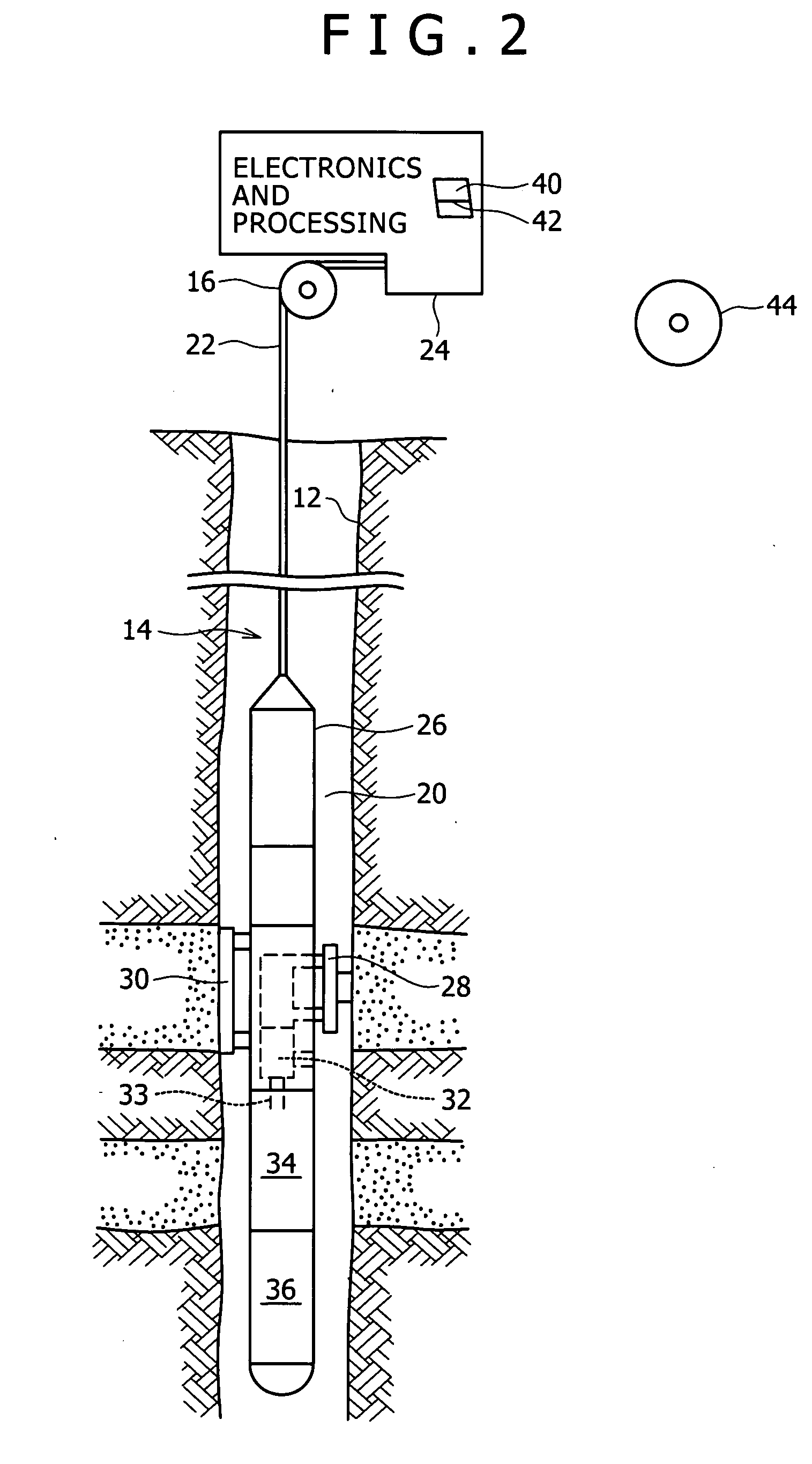
[0049] The present invention is applicable to oilfield exploration and development in areas such as downhole fluid analysis using one or more fluid analysis modules in Schlumberger's Modular Formation Dynamics Tester (MDT), for example.

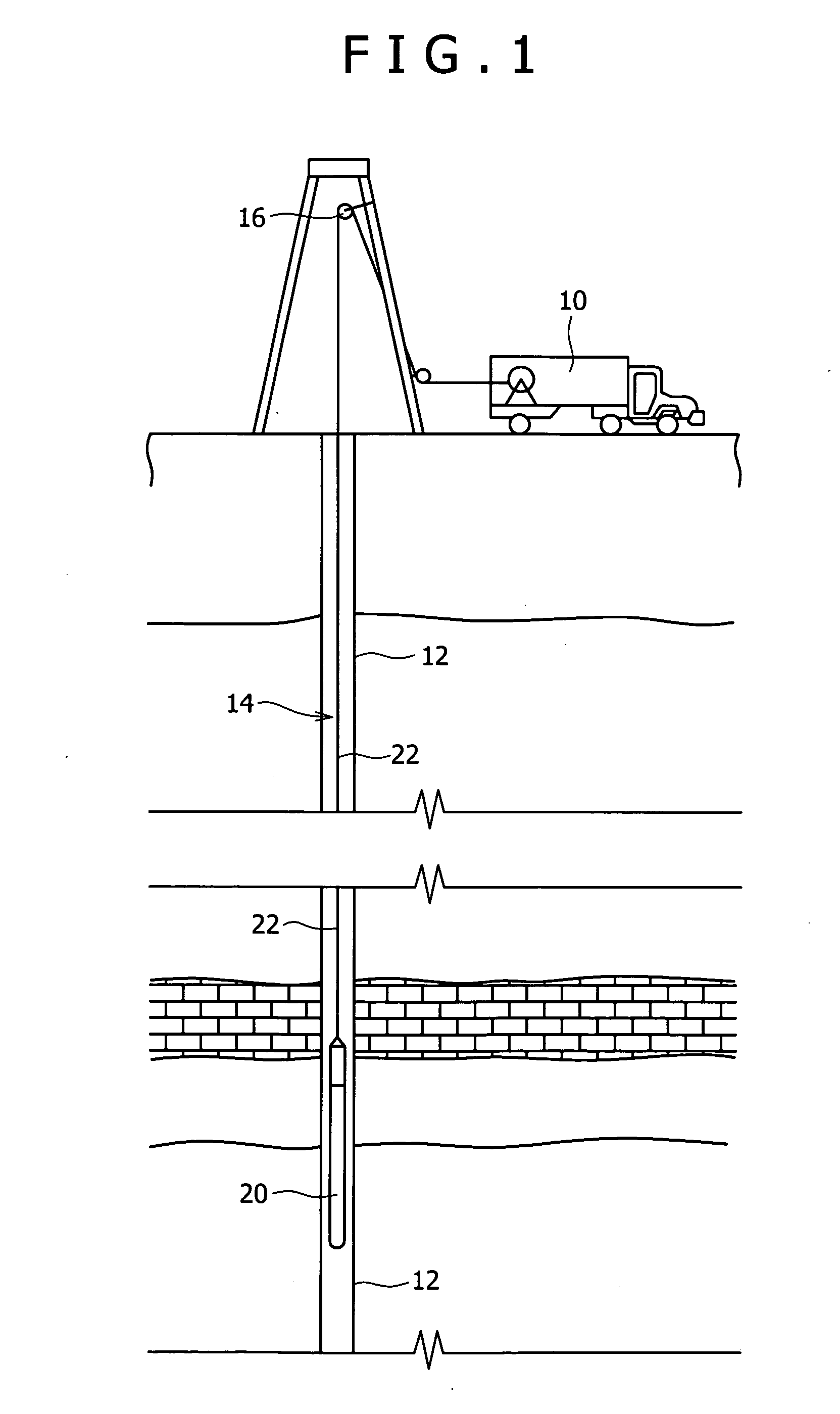
[0050]FIG. 1 is a schematic rep...


PUM


Abstract

Methods and apparatus for downhole analysis of formation fluids by isolating the fluids from the formation and / or borehole in a pressure and volume control unit that is integrated with a flowline of a fluid analysis module and determining fluid characteristics of the isolated fluids. Parameters of interest may be derived for formation fluids in a static state and undesirable formation fluids may be drained and replaced with formation fluids that are suitable for downhole characterization or surface sample extraction. Isolated formation fluids may be circulated in a loop of the flowline for phase behavior characterization. Real-time analysis of the fluids may be performed at or near downhole conditions.

Description

RELATED APPLICATION DATA [0001] The present application claims priority under 35 U.S.C. § 120 as a continuation-in-part of U.S. Non-Provisional Application Ser. No. 10 / 908,161 (Attorney Docket No. 20.2974) naming D. Freemark et al. as inventors, and filed Apr. 29, 2005, now pending, the aforementioned application being incorporated herein by reference in its entirety for all purposes.FIELD OF THE INVENTION [0002] The present invention relates to the field of analysis of downhole fluids of a geological formation for evaluating and testing the formation for purposes of exploration and development of hydrocarbon-producing wells, such as oil or gas wells. More particularly, the present invention is directed to methods and apparatus suitable for isolating formation fluids and characterizing the isolated fluids downhole utilizing, in part, a pressure and volume control unit. BACKGROUND OF THE INVENTION [0003] Downhole fluid analysis is an important and efficient investigative technique ty...

Claims


Application Information

Patent Timeline
IPC IPC(8): E21B47/08
CPCE21B49/10G01N2011/006G01N9/36G01N7/00
Inventor TERABAYASHI, TORUCHIKENJI, AKIHITOYAMATE, TSUTOMUMULLINS, OLIVER C.KURKJIAN, ANDREW L.ELSHAHAWI, HANI
Owner SCHLUMBERGER TECH CORP
Learn More