Manufacturing carbon fiber reinforced ceramics as brake discs

a technology of carbon fiber reinforced ceramics and brake discs, which is applied in the direction of friction linings, mechanical devices, actuators, etc., can solve the problems of difficult manufacturing without defects, time-consuming and expensive, and difficult methods of reliable friction-bearing ceramic structures, so as to preserve the superior thermal conductivity and mechanical properties of carbon fiber, the effect of sic/c bonding greater degr

Inactive Publication Date: 2006-11-02
GRAFTECH INT HLDG INC
View PDF6 Cites 39 Cited by
  • Summary
  • Abstract
  • Description
  • Claims
  • Application Information

AI Technical Summary

Benefits of technology

[0012] An advantage of at least one embodiment of the present invention is that CFRC structures, such as brake components, are formed in much shorter periods of time than by conventional methods.
[0013] Another advantage of at least one embodiment of the present invention is that the pre-ceramic polymer impregnation and pyrolysis process achieves a greater degree of SiC / C bonding than conventional methods of forming CFRC structures.
[0014] Another advantage of at least one embodiment of the present invention is that the pre-ceramic polymer impregnation and pyrolysis process preserves the superior thermal conductivity and mechanical properties of carbon fiber since no carbon is consumed or reacted during the pre-ceramic polymer impregnation and pyrolysis process or the subsequent high-temperature heat treatment process.

Problems solved by technology

Methods of manufacturing reliable friction-bearing ceramic structures are difficult, time consuming and expensive.
However, most ceramic structures are also brittle and difficult to manufacture without defects.
However, the lengthy heating and infiltration times render the above identified methods of manufacturing CFRC structures expensive and often impractical for many applications.
Moreover, in the simple mixing method described, the bonding of the carbon fibers and the binder of the pre-ceramic polymer coating slurry are not optimal.
Similarly, the pyrolysis processes of these methods produce less than optimal SiC / C bonding.

Method used


Image

  • Manufacturing carbon fiber reinforced ceramics as brake discs
  • Manufacturing carbon fiber reinforced ceramics as brake discs
  • Manufacturing carbon fiber reinforced ceramics as brake discs

Examples


Embodiment Construction

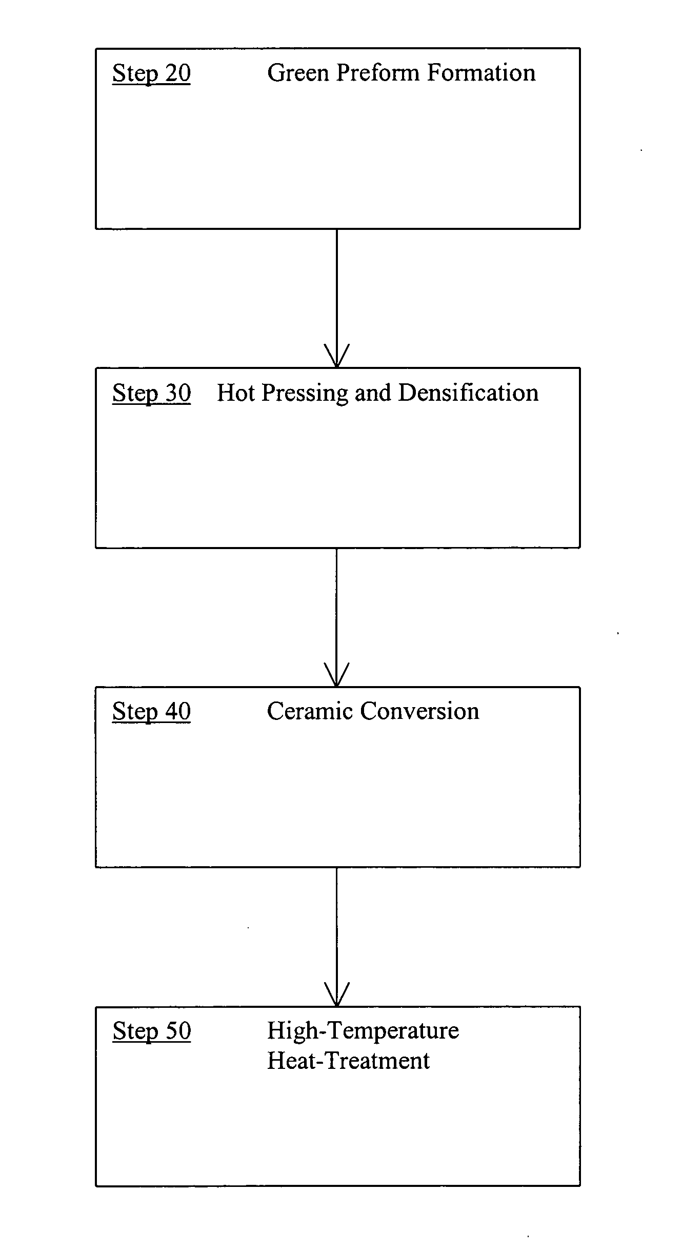
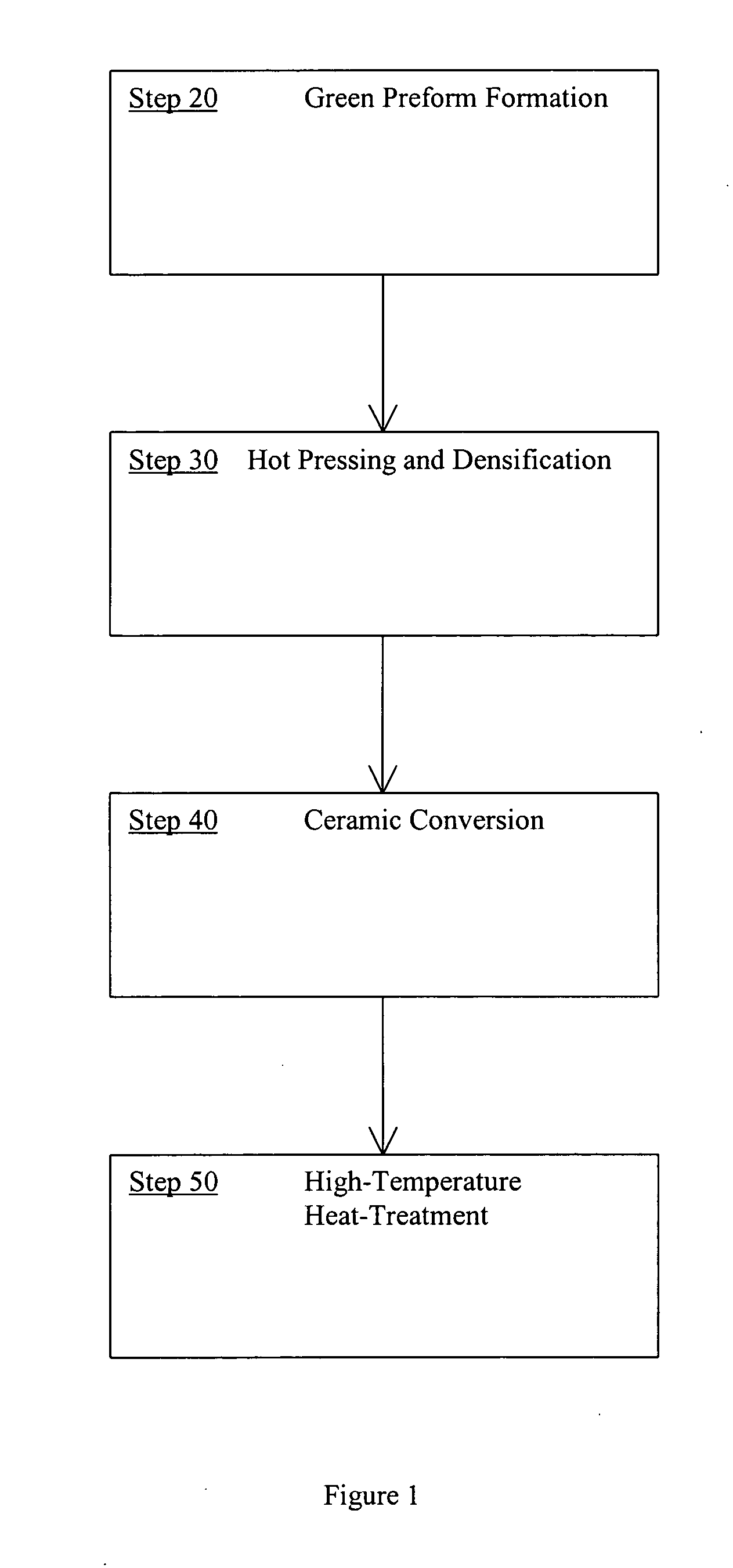
[0021] A method of forming a CFRC material suitable for use in thermal structural applications, such as friction components, is provided by impregnating an at least partially carbonized carbon / carbon composite preform with a pre-ceramic polymer. The pre-ceramic polymer impregnated carbon / carbon composite is then heat-treated so that the pre-ceramic polymer is pyrolytically decomposed. Finally, the carbon / ceramic composite preform is high-temperature heat treated so as to form a carbon fiber reinforced ceramic body.

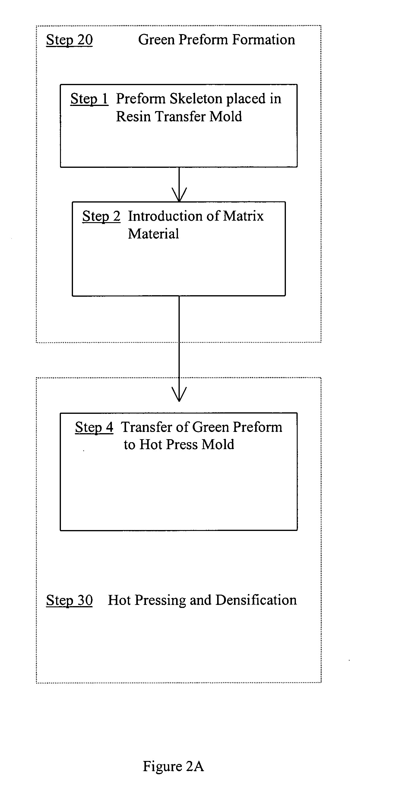
[0022] The carbon / carbon composite material is formed by resistance heating of a mixture of a carbon-based reinforcement material, such as carbon fibers, and a matrix material, such as powdered pitch. The resistive heating step is accompanied by application of mechanical pressure to density the mixture. After hot-pressing, the compressed composite or “preform” is preferably subjected to one or more cycles of infiltration and baking steps employing a carbonizable resin, pi...


PUM

PropertyMeasurementUnit
temperatureaaaaaaaaaa

Abstract

A carbon fiber reinforced ceramic brake disc or pad is formed from a rapidly hot-pressed carbon / carbon composite material. First, a reinforcement material, preferably including carbon fibers, is combined with a carbonizable matrix material to form a green preform. The green preform is heated and a portion of the matrix material is at least partially carbonized so as to form a carbon / carbon composite. Optionally, a carbonizable material is introduced into voids in the carbon / carbon composite. The product is then heated to carbonize the carbonizable material. The carbonizable material infiltration and baking steps are optionally repeated to increase the density of the composite. A pre-ceramic polymer material is introduced into voids of the carbon / carbon composite and heat-treated so as to pyrolytically decompose the pre-ceramic polymer. Finally, the carbon / ceramic composite is then high-temperature heat treated so as to form a carbon fiber reinforced ceramic material.

Description

BACKGROUND OF THE INVENTION [0001] The present application relates to a method for forming carbon reinforced fiber ceramic structures suitable for high temperature, friction-bearing applications. The present application relates more particularly to a method for forming carbon reinforced fiber ceramics from at least partially carbonized carbon / carbon composite materials. It finds particular application in conjunction with a carbon fiber reinforced ceramic material formed from a carbonized carbon / carbon composite material which itself is formed by resistance heating of combinations of carbon fiber and binder / matrix materials during application of a compressive force and will be described with particular reference thereto. [0002] Methods of manufacturing reliable friction-bearing ceramic structures are difficult, time consuming and expensive. Ceramic structures are desirable because of their exceptional high-temperature performance, relative lightness of weight, extreme hardness, and h...

Claims


Application Information

Patent Timeline
Patent Type & Authority Applications(United States)
IPC IPC(8): C01B31/00
CPCC04B35/522C04B35/571C04B35/64C04B35/83C04B2235/3217C04B2235/3232F16D2200/0047C04B2235/465C04B2235/483C04B2235/666C04B2235/77F16D69/023C04B2235/3244
Inventor HUANG, DAI
Owner GRAFTECH INT HLDG INC
Why Eureka
Try Eureka