Light-beam scanning device

a scanning device and beam technology, applied in the field of light beam scanning devices, can solve the problems of increasing factor causing failures, reducing the scanning area and/or reducing the scanning area and/or thickness. , to achieve the effect of facilitating the reduction of the area and/or thickness of the light beam scanning device, reducing power consumption, and increasing flexibility

Active Publication Date: 2006-11-02
NAT INST OF ADVANCED IND SCI & TECH
View PDF6 Cites 36 Cited by
  • Summary
  • Abstract
  • Description
  • Claims
  • Application Information

AI Technical Summary

Benefits of technology

[0033] The present invention having the above features can generate a plate wave in the base plate supporting the mirror portion, by the vibration source member, such as a piezoelectric element, so as to produce a rotational moment in the mirror portion according to the plate wave and induce a large torsional amplitude in the mirror portion by means of a resonance phenomenon.
[0034] The present invention has at least the following advantages. However, the embodiments may not have the following advantages, or any advantages, without departing from the scope of the present invention.
[0037] (3) The center-of-gravity position of the mirror portion can be slightly deviated from the connection position of the torsion bar portion to effectively oscillate the mirror portion while preventing the occurrence of hysteresis.
[0038] (4) Simplification in structural and reduction in fabrication cost can be facilitated.
[0040] (6) A piezoelectric film serving as the vibration source member can have substantially reduced power consumption.
[0041] (7) The piezoelectric film can be arranged with increased flexibility to facilitate reduction in area and / or thickness of the light-beam scanning device.

Problems solved by technology

The requirement of having the electrode portion 5 formed in at least a peripheral region or a surface of the mirror 2, the pads 4a, 4b connected to the torsion bars 3a, 3b, the fixed electrodes 7a, 7b disposed, respective, on opposite lateral sides of the top surface of the support substrate 1 through the insulator 6, and the pads 8a, 8b connected to the fixed electrodes 7a, 7b, causes structural complexity, and increases in factor causing failures, lost manufacturing time and increased cost.
Moreover, a thickness of this light beam scanner is inevitably increased in not only the X-Y directions but also the Z-axis direction, which causes difficulties in achieving a thin structure.

Method used


Image

  • Light-beam scanning device
  • Light-beam scanning device
  • Light-beam scanning device

Examples


first embodiment

]

[0091]FIG. 6 is a perspective view of a light-beam scanning device according to a first exemplary, non-limiting embodiment of the present invention.

[0092] A base plate 10 is fabricated by subjecting a metal material having a substantially square shape with a thickness of about 30 to 50 μm to an etch process or a press working to form the plate material so as to be partly removed while leaving a torsion beam portion 12 and a mirror portion 13 therein. Only one end of the base plate 10 is supported by a support member 16 in a cantilevered manner.

[0093] The base plate 10 is made of a metal material, such as SUS 304 having electrical conductivity or SUS 430 having electrical conductivity and low thermal expansion coefficient, so as to eliminate the need for forming a lower electrode to facilitate reduction in size and simplification in structure of the light-beam scanning device.

[0094] The mirror portion 13 is formed to have a length l1 of about 1.1 mm and a width b1 of about 100 to...

second embodiment

[Second Embodiment]

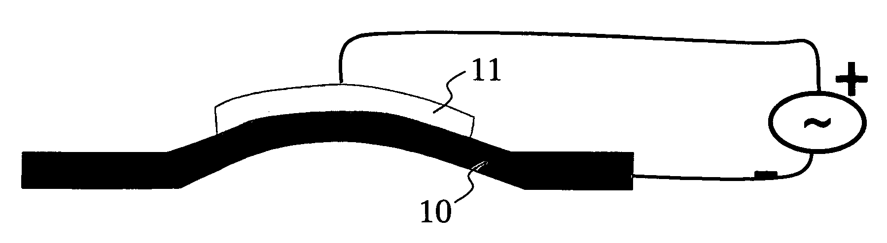
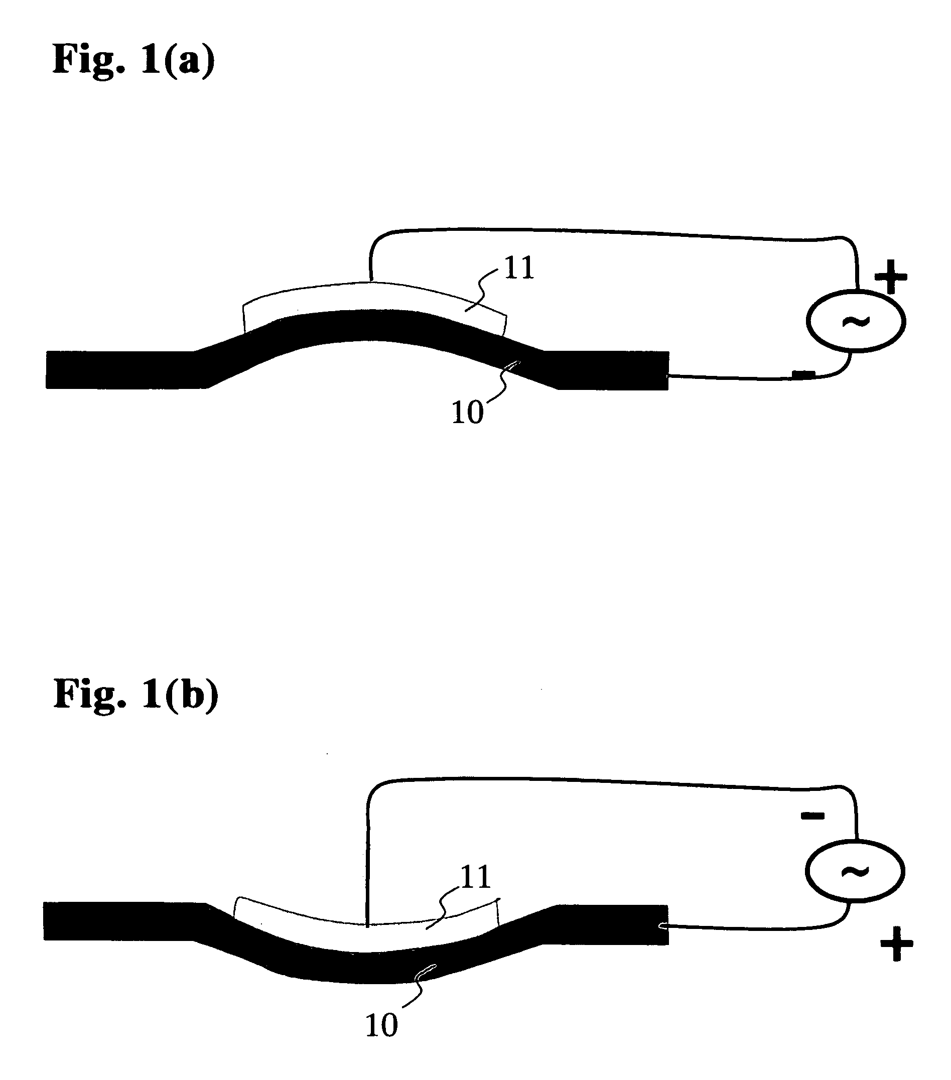
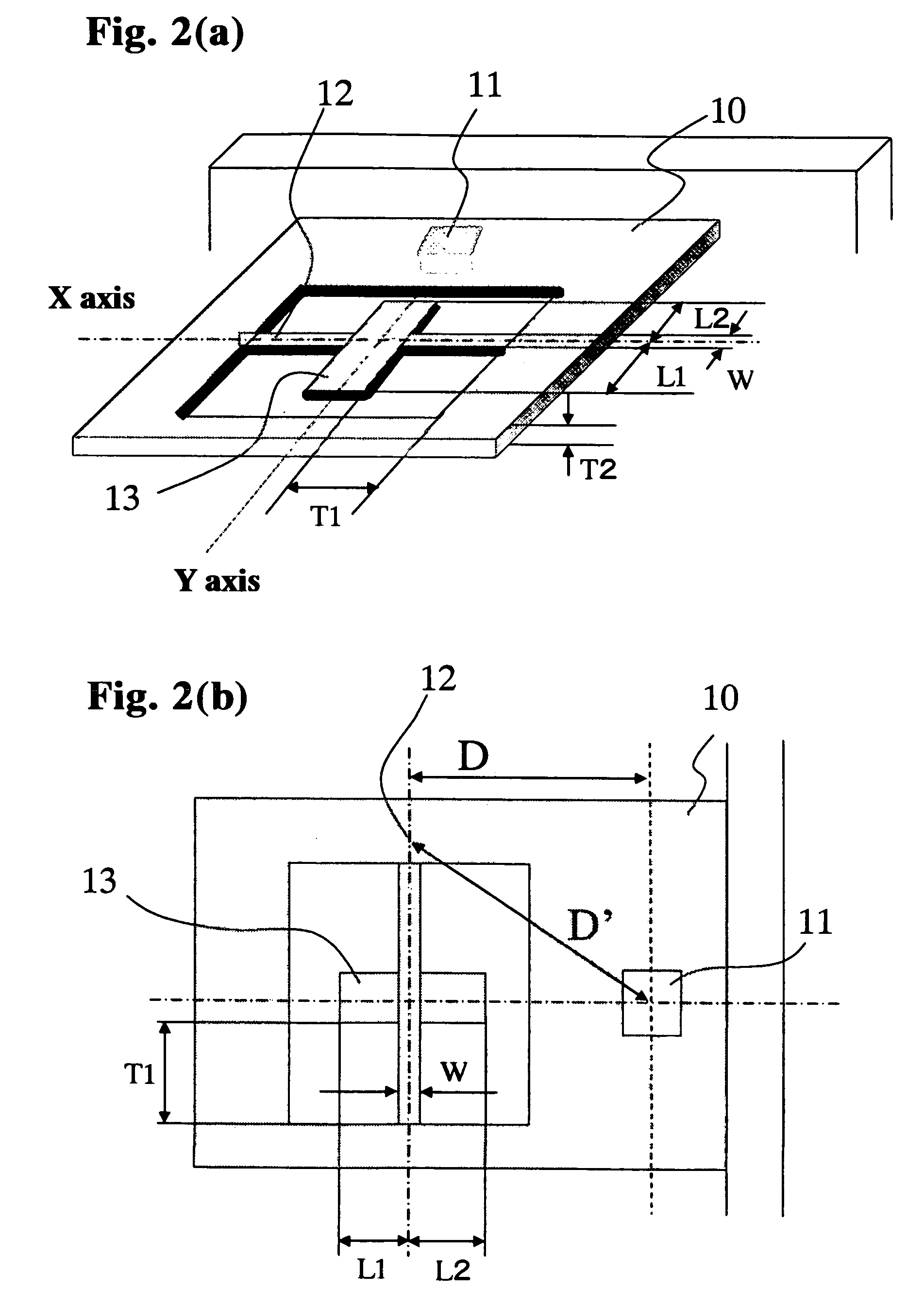
[0116] FIGS. 11(a) and 11(b) show a light-beam scanning device according to a second exemplary, non-limiting embodiment of the present invention, which comprises a base plate 10, a piezoelectric film 11, a torsion beam portion 12 and a mirror portion 13. FIGS. 11(a) and 11(b) are, respectively, a perspective view and a top plan view of the light-beam scanning device.

[0117] Except that a portion of a free end of the base plate 10 is cut out to form a pair of opposite lateral portions 19, 19 each supporting a corresponding one of opposite ends of the torsion beam portion 12, in a cantilever configuration, the light-beam scanning device illustrated in FIGS. 11(a) and 11(b) has the same structure as that in the first embodiment.

[0118] As shown in FIG. 12(a), the device in FIGS. 11(a) and 11(b) is designed such that L1=L2, and form a minimum amplitude Amin of vibrations in the base plate (node of a plate wave) at a position slightly deviated from an axis X-X of the t...


PUM


Abstract

A light-beam scanning device includes a base plate having a torsion beam portion formed therein, and a mirror portion supported by the torsion beam portion and adapted to be oscillated. The light-beam scanning device includes one of a piezoelectric member, a magnetostrictive member and a permanent magnet member, which is fixed to or formed as a portion of the base plate. The mirror portion supported by the torsion beam portion is oscillated by a plate wave that is induced in the base plate by applying a voltage or electric field to the piezoelectric, magnetostrictive or permanent magnet member. The light-beam scanning device can efficiently generate a torsional oscillation in the mirror portion in a simplified structure.

Description

[0001] This application claims foreign priority under 35 USC §119 based on Japanese Patent Application No. 2005-115352, filed on Apr. 13, 2005, the contents of which is incorporated herein by reference in its entirety. This foreign priority claim is being made concurrently with the filing of this application. TECHNICAL FIELD [0002] The present invention relates to a light beam scanner for scanningly deflecting a light beam, and more particularly to a light-beam scanning device designed to rotationally oscillate a micromirror supported by a torsion beam (torsion bar) so as to deflect a light beam. BACKGROUND ART [0003] In the related art, a light beam scanner for scanningly deflecting a light beam, such as a laser beam, is used in various optical apparatuses, such as barcode readers, laser printers and head-mounted displays, or as a light pickup element of an optical input device for infrared cameras or the like. In connection with this type of light beam scanner, there has been prop...

Claims


Application Information

Patent Timeline
Patent Type & Authority Applications(United States)
IPC IPC(8): G02B26/08
CPCG02B26/0858G02B26/085
Inventor AKEDO, JUNMAXIM, LEBEDEV
Owner NAT INST OF ADVANCED IND SCI & TECH
Why Eureka
Try Eureka