Inverter bridge short-circuit protection scheme

a short-circuit protection and inverter bridge technology, applied in emergency protective arrangements for limiting excess voltage/current, dc-ac conversion without reversal, dc source parallel operation, etc., can solve the problems of voltage spike, igbt destruction, and current through igbt rising slowly

Active Publication Date: 2006-11-02
SMC ELECTRICAL PROD +1
View PDF5 Cites 26 Cited by
  • Summary
  • Abstract
  • Description
  • Claims
  • Application Information

AI Technical Summary

Benefits of technology

[0017] When shutting off switches, whether under normal operating conditions or fault conditions, it is essential to shut off switches in each half branch sequentially from outer to inner, as is known in the art. The present invention facilitates safe shutting off of outer switches by assuring that the outer switches always desaturate and shut-off first.
[0048] These above various aspect of the invention mitigate damage from Type I and Type II faults by reliably assuring that outer switches of the inverter bridge will desaturate first, thereby guaranteeing that a switching-off of the switches occurs in the necessary and proper sequence, without requiring a specialized inverter controller.
[0049] While using lower transconductance and / or lower magnitude excitation control signals for outer switches is beneficial, the overall benefits achieved would not be the same if similar values were applied to inner switches, since safe shutting off of the inverter bridge depends upon shutting off each half-branch sequentially from the outermost transistor to the innermost transistor. Each switch is designed to handle only a percentage of the bus voltage, and by switching off an inner transistor before an outer transistor, the whole of the bus voltage may be placed across the shut-off inner transistor. Because of the position of the inner transistor in the topology, this results in the destruction of the inner transistor.

Problems solved by technology

Typically, a Type I fault is the result of a fault inside the drive (for example, an IGBT failure or an output fault with low inductance).
However, in three-or-more (multiple) level inverter bridges, which have more than two IGBT switches involved in the fault current path, the desaturation sequence of IGBT switches becomes unpredictable, which may cause IGBT destruction.
The impedance in the circuit undergoing fault is typically high, resulting in the current through the IGBT rising slowly.
However, such switching while in saturation results in a voltage spike that may destroy the transistor.
Type II faults involve a short-circuit path inductance which causes a limited di / dt current increase, which will allow the current to rise well above the maximum rated current of the IGBT, but will not allow the IGBT to enter desaturation.
Adding additional circuitry to an inverter bridge to cut off power to the inductive load, without commanding off the IGBTs, as a practical matter, increases the leakage inductance of the inverter bridge circuit, thereby causing otherwise innocuous current switching di / dts to generate harmful voltage spikes.
In comparison, if the switches are commanded off during a Type II fault and the fault current rises above the maximum rated current of the IGBT, then the IGBT will most likely be destroyed by the voltage spike generated by the negative current di / dt.
However, this increases losses and does not address the situation when the inductance itself is part of the short-circuit.
However, once an IGBT reaches desaturation current levels under a fault condition (t4), there is very little time to turn off the switch before there is thermal damage to the IGBT.
To date, in conventional designs, there is always a fault current inductance that will cause any inverter bridge to risk destruction when commanding the IGBTs to an off-state during a Type II fault.
Moreover, with conventional inverter bridges, even when the inverter bridge controller commands switches off in a proper sequence, since desaturation ordinarily occurs randomly among the switches in series, destruction of the switches may nonetheless occur.

Method used


Image

  • Inverter bridge short-circuit protection scheme
  • Inverter bridge short-circuit protection scheme
  • Inverter bridge short-circuit protection scheme

Examples


Embodiment Construction

[0057] In the present disclosure, in the context of switching, the terms “on-state,”“conducting,” and “closed” are interchangeable, as are the terms “off-state,”“non-conducting,” and “open”.

[0058] An aspect of the invention is using IGBTs having lower transconductance values (gm) for the outer switches relative to the transconductance values of the inner switches. By using lower transconductance IGBTs for the outer switches, the outer switches will always desaturate before the inner switches, even when equivalent +VGE levels and ordinary inverter bridge controllers are used.

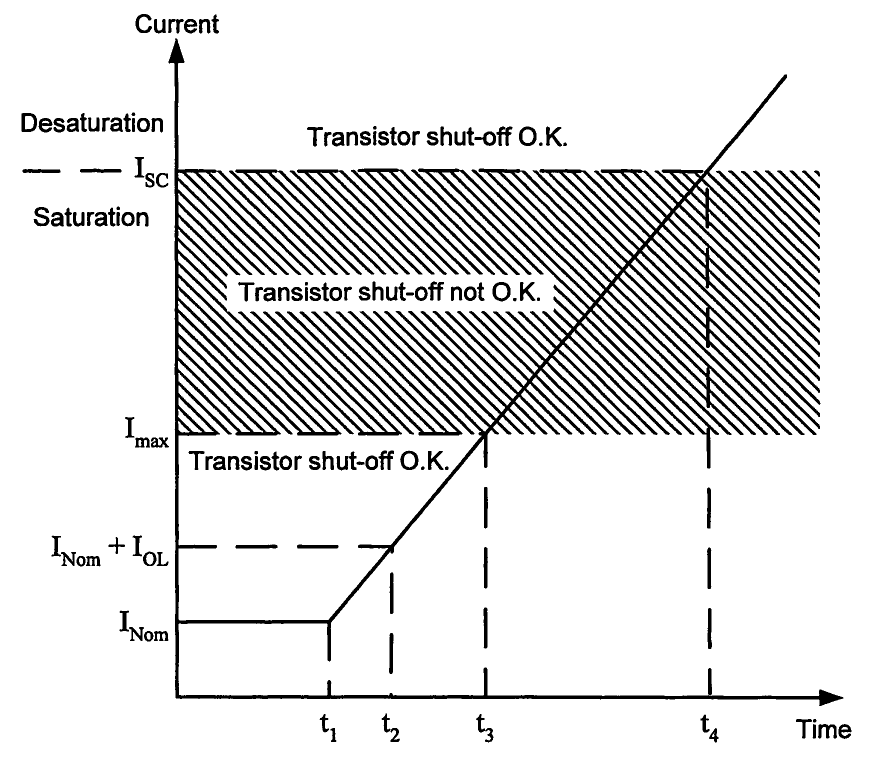
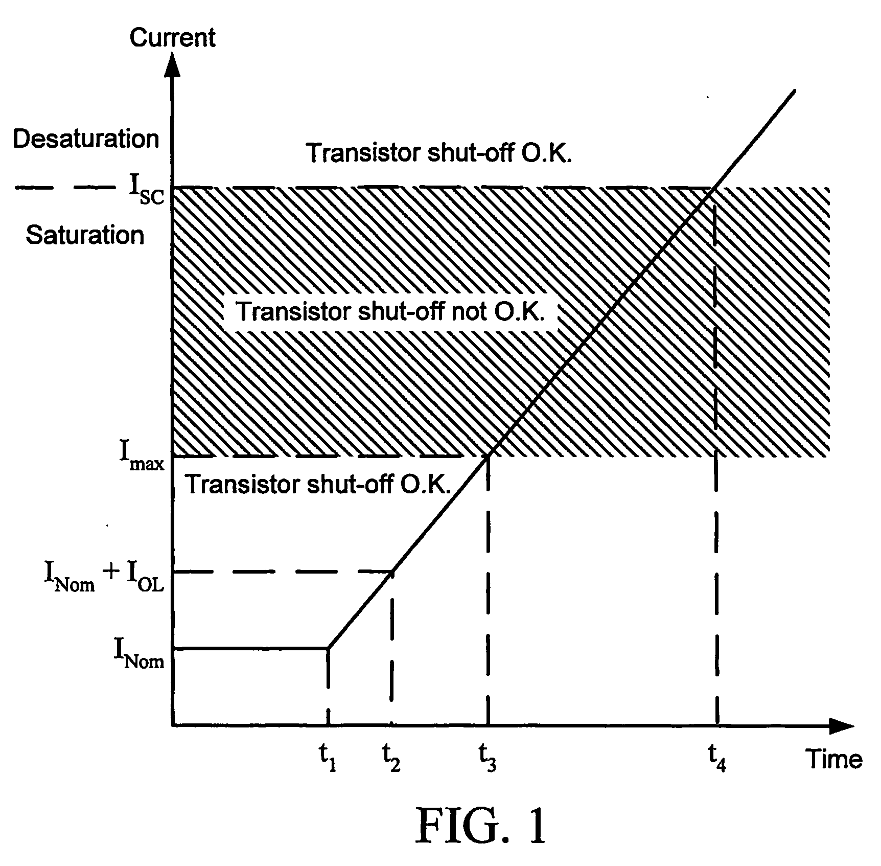
[0059] Several techniques are known in the art for determining transconductance. For example, with IGBTs, an easy way to screen for the transconductance of each IGBT is by measuring the collector-to-emitter voltage drop at rated IGBT current and with +VGE equal to 15V. Another way to screen for transconductance is to create a short-circuit Type I fault and measure the current though the switch: the higher the t...


PUM


Abstract

A fault handling system for short circuit recovery in three-phase multiple-level inverter bridges, used to drive inductive loads, to assure a proper sequence for turning-off switches in the inverter bridge. Switches are selected for use in the inverter bridge so that outer switches toward the most positive and most negative bus voltage levels of the inverter bridge have lower transconductances than inner switches closest to an output phase of the inverter bridge. Additionally, driver cards driving outer switches utilize lower magnitude excitation control signals than driver cards driving inner switches. Driver cards driving outer switches, when detecting desaturation of an on-state switch, are set to automatically command the outer switch to an off-state, whereas driver cards driving inner switches wait for instructions from a controller before taking action.

Description

BACKGROUND OF THE INVENTION [0001] 1. Field of the Invention [0002] Fault handling in inverter bridges utilizing Insulated Gate Bipolar Transistors (IGBTs) and similar switching devices, such as inverter bridges utilized with three-phase AC motors. [0003] 2. Description of the Related Art [0004] Inverter bridges provide controlled energy used to drive inductive loads. A plurality of switches within the inverter bridge are sequentially switched to vary the inverter bridge's output voltage. Typically, output is a three-phase alternating current voltage. For a general background description of inverter bridge topologies and switching schemes, PCT Publications WO 02 / 37654 A2 published 10 May 2002 and WO 2004 / 015851 A2 published 19 Feb. 2004 are incorporated herein by reference. [0005] In conventional inverter bridges, fault conditions (short-circuits) can be characterized as falling into one of two categories. A first category is a Type I fault. Typically, a Type I fault is the result o...

Claims


Application Information

Patent Timeline
Patent Type & Authority Applications(United States)
IPC IPC(8): H02M7/5387H02H3/18H02M1/32H02M1/38H02M7/487
CPCH02M1/32H02M7/53871H02M7/487H02M1/38
Inventor NOJIMA, GERALDO
Owner SMC ELECTRICAL PROD
Why Eureka
Try Eureka