Inverter bridge controller implementing short-circuit protection scheme

a short-circuit protection and controller technology, applied in the direction of dc-ac conversion without reversal, process and machine control, instruments, etc., can solve the problems of destroying transistors, voltage spikes, slow rise of current through igbts, etc., to improve statistical switch survivability, improve the likelihood of switch survivability, and fast and safe shut down

Active Publication Date: 2005-12-22
EATON INTELLIGENT POWER LTD +1
View PDF7 Cites 64 Cited by
  • Summary
  • Abstract
  • Description
  • Claims
  • Application Information

AI Technical Summary

Benefits of technology

[0050] These above aspects of the invention mitigate damage from Type I and Type II faults. When saturation occurs, by delaying until a sooner of desaturation of the most outer transistor remaining in an on-state and the expiration of the delay period, the statistical likelihood of switch survivability is markedly improved. While waiting until the brink of destruction to turn a switch off may still result in destruction caused by the −di / dt voltage spike if the switch is still saturated, statistical switch survivability is improved in comparison to when a switch conducting an overload current is allowed to cross into saturation after being commanded to an off-state, or is immediately commanded to an off-state while already in saturation. The closer the delay period is set to the time that destruction of the switches will occur, the greater the probability that desaturation will occur, in comparison to commanding switches off as soon as an overload is detected.
[0051] Further, by shunting the overload current to a neutral level a lower impedance path is offered to the overload current, thereby immediately desaturating the most outer switch remaining in an on-state, allowing the inverter bridge to be shut down quickly and safely.

Problems solved by technology

Typically, a Type I fault is the result of a fault inside the drive (for example, an IGBT failure or an output fault with low inductance).
The impedance in the circuit undergoing fault is typically high, resulting in the current through the IGBT rising slowly.
However, such switching while in saturation results in a voltage spike that may destroy the transistor.
Type II faults involve a short-circuit path inductance which causes a limited di / dt current increase, which will allow the current to rise well above the maximum rated current of the IGBT, but will not allow the IGBT to enter desaturation.
Existing solutions to this problem generally create other problems.
For example, adding additional circuitry to an inverter bridge to cut off power to the inductive load, without commanding off the IGBTs, as a practical matter, increases the leakage inductance of the inverter bridge circuit, thereby causing otherwise innocuous current switching di / dts to generate harmful voltage spikes.
In comparison, if the switches are commanded off during a Type II fault and the fault current rises above the maximum rated current of the IGBT, then the IGBT will most likely be destroyed by the voltage spike generated by the negative current di / dt.
Because of inherent time delays which increase with the power-handling capacity of the switch used, the fault current continues to rise, entering a forbidden region for switch shut-off before the controller can act, or before a switch commanded to shut-off actually does shut-off.
However, this increases losses and does not address the situation when the inductance itself is the cause of the short-circuit.
However, once an IGBT reaches desaturation current levels under a fault condition (t4), there is very little time to turn off the switch before there is thermal damage to the IGBT.
To date, in conventional designs, there is always a fault current inductance that will cause any inverter bridge to risk destruction when commanding the IGBTs to an off-state during a Type II fault.
Moreover, with conventional inverter bridges, even when the inverter bridge controller commands switches off in a proper sequence, since desaturation ordinarily occurs randomly among the switches in series, destruction of the switches may nonetheless occur.

Method used


Image

  • Inverter bridge controller implementing short-circuit protection scheme
  • Inverter bridge controller implementing short-circuit protection scheme
  • Inverter bridge controller implementing short-circuit protection scheme

Examples


Embodiment Construction

[0068] In the present disclosure, in the context of switching, the terms “on-state,”“conducting,” and “closed” are interchangeable, as are the terms “off-state,”“non-conducting,” and “open”.

[0069]FIGS. 6A, 6B, 7A, 7B, 8A, and 8B are a flow diagram illustrating exemplary embodiments for controlling an inverter bridge. The embodiments focus on a single phase output of the inverter bridge, representative of what is done for each of the three phase outputs.

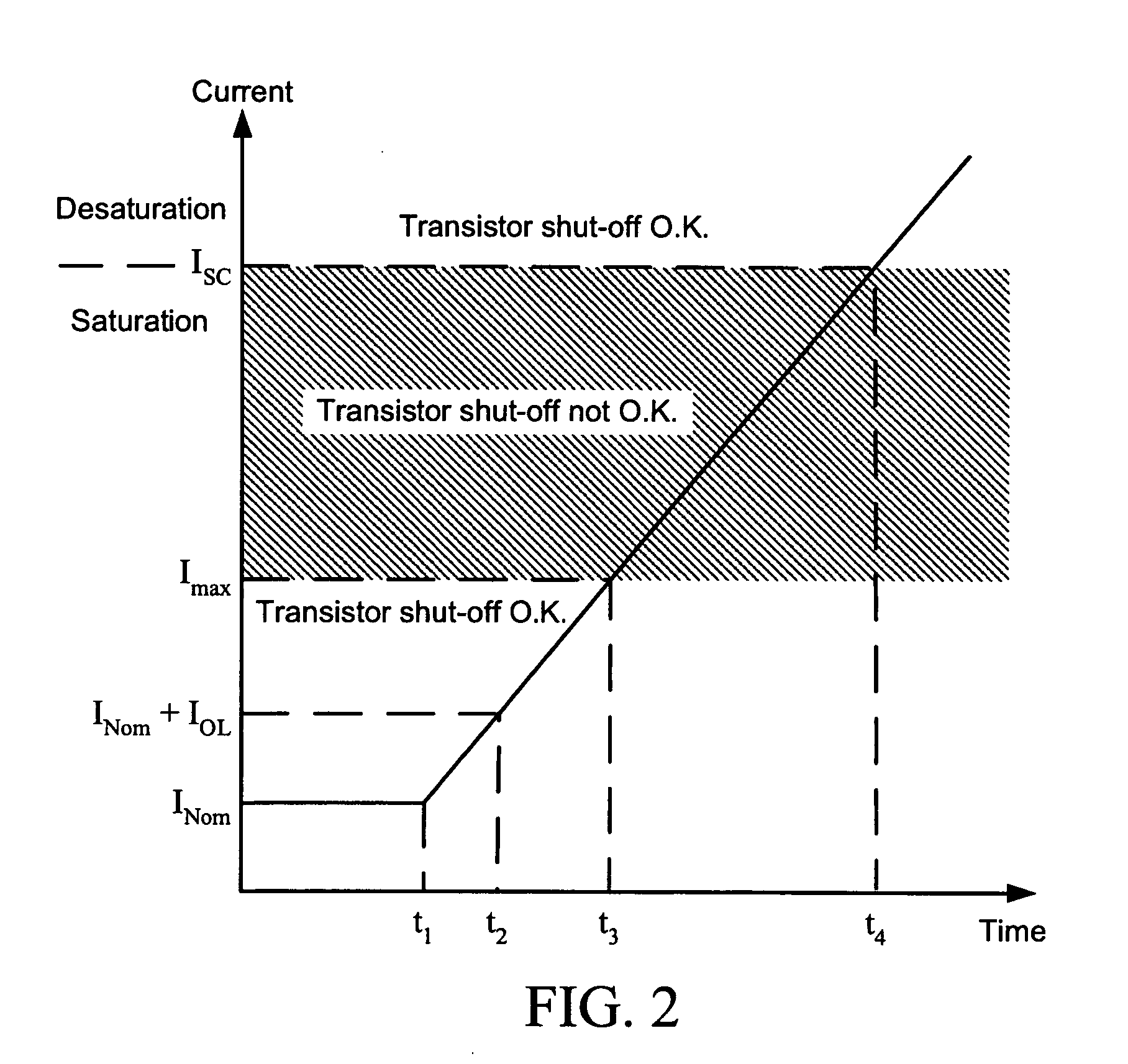
[0070] Referring to FIG. 6A, the instantaneous output current Io of the phase is compared to a rated nominal current the rated nominal current (INom) of switches of the branch plus an overload current threshold (IOL) (step 601). INom is the nominal maximum current (100% current) that a switch can withstand without regard to temperature (provided the temperature is inside the rated range of the switch). In comparison, Imax is a maximum rated current of the switches of the branch, which typically is a maximum continuous current a swit...


PUM


Abstract

A fault handling system for short circuit recovery in three-phase multiple-level inverter bridges, used to drive inductive loads, which waits for either desaturation of switches or expiration of a delay period based upon an amount of time before saturated switches are damaged before commanding off switches that are saturated, and which artificially creates a dead-short across the three-phase output to force switches conducting a fault current to desaturate. By delaying the switching-off of the inverter bridge during a fault, waiting for desaturation to occur, the statistical likelihood of switch survival is improved.

Description

BACKGROUND OF THE INVENTION [0001] 1. Field of the Invention [0002] Fault handling in inverter bridges utilizing Insulated Gate Bipolar Transistors (IGBTs) and similar switching devices, such as inverter bridges utilized with three-phase AC motors. [0003] 2. Description of the Related Art [0004] Inverter bridges provide controlled energy used to drive inductive loads. A plurality of switches within the inverter bridge are sequentially switched to vary the inverter bridge's output voltage. Typically, output is a three-phase alternating current voltage. For a general background description of inverter bridge topologies, sequential switching schemes, and circuits and procedures for performing sequential switching schemes, PCT Publications WO 02 / 37654 A2 published 10 May 2002 and WO 2004 / 015851 A2 published 19 Feb. 2004 are incorporated herein by reference. An exemplary three-level inverter bridge topology is illustrated in FIG. 1. [0005] In conventional inverter bridges, fault conditio...

Claims


Application Information

Patent Timeline
Patent Type & Authority Applications(United States)
IPC IPC(8): H02M1/00H02M1/12H02M1/38H02M7/48H02M7/487
CPCH02H3/025H02M7/487H02M1/38H02H7/1227H02M1/32
Inventor NOJIMA, GERALDO
Owner EATON INTELLIGENT POWER LTD
Why Eureka
Try Eureka