Dual cassette load lock

a dual-cassette, load lock technology, applied in the direction of charging manipulation, lighting and heating apparatus, furnaces, etc., can solve the problem of significant increase in the time of semiconductor processing equipment, and achieve the effect of increasing the throughput of wafers through the workpiece processing system

Inactive Publication Date: 2006-11-02
TOSHIMA MASATO M +6
View PDF13 Cites 13 Cited by
  • Summary
  • Abstract
  • Description
  • Claims
  • Application Information

AI Technical Summary

Benefits of technology

[0004] In accordance with the preferred embodiment of the present invention, a workpiece loading interface is presented for inclusion within a workpiece processing system. The workpiece loading interface includes two separate chambers. Each chamber may be separately pumped down. Thus, while a first cassette of workpieces, typically wafers, from a first chamber are being accessed, a second cassette or wafers may be loaded in the second chamber and the second chamber may then be pumped down. This can significantly increase throughput of wafers through the workpiece processing system.
[0005] In the preferred embodiment, each chamber is designed to minimize intrusion to a clean room. Thus a door to each chamber has a mechanism which, when opening the door, first moves the door slightly away from an opening in the chamber and then the door is moved down parallel to the chamber. After the door is opened, a cassette of wafers is lowered through the opening in a motion much like a drawbridge. The cassette of wafers is on a support with no side panels, facilitating the replacement of a cassette of processed wafers with a cassette of unprocessed wafers by an automated device.

Problems solved by technology

This significantly increases the time the semiconductor processing equipment is idle while waiting for a cassette of processed wafers to be exchanged for a cassette of unprocessed wafers and subsequent pumping down of the wafer queuing station.

Method used


Image

  • Dual cassette load lock
  • Dual cassette load lock
  • Dual cassette load lock

Examples


Embodiment Construction

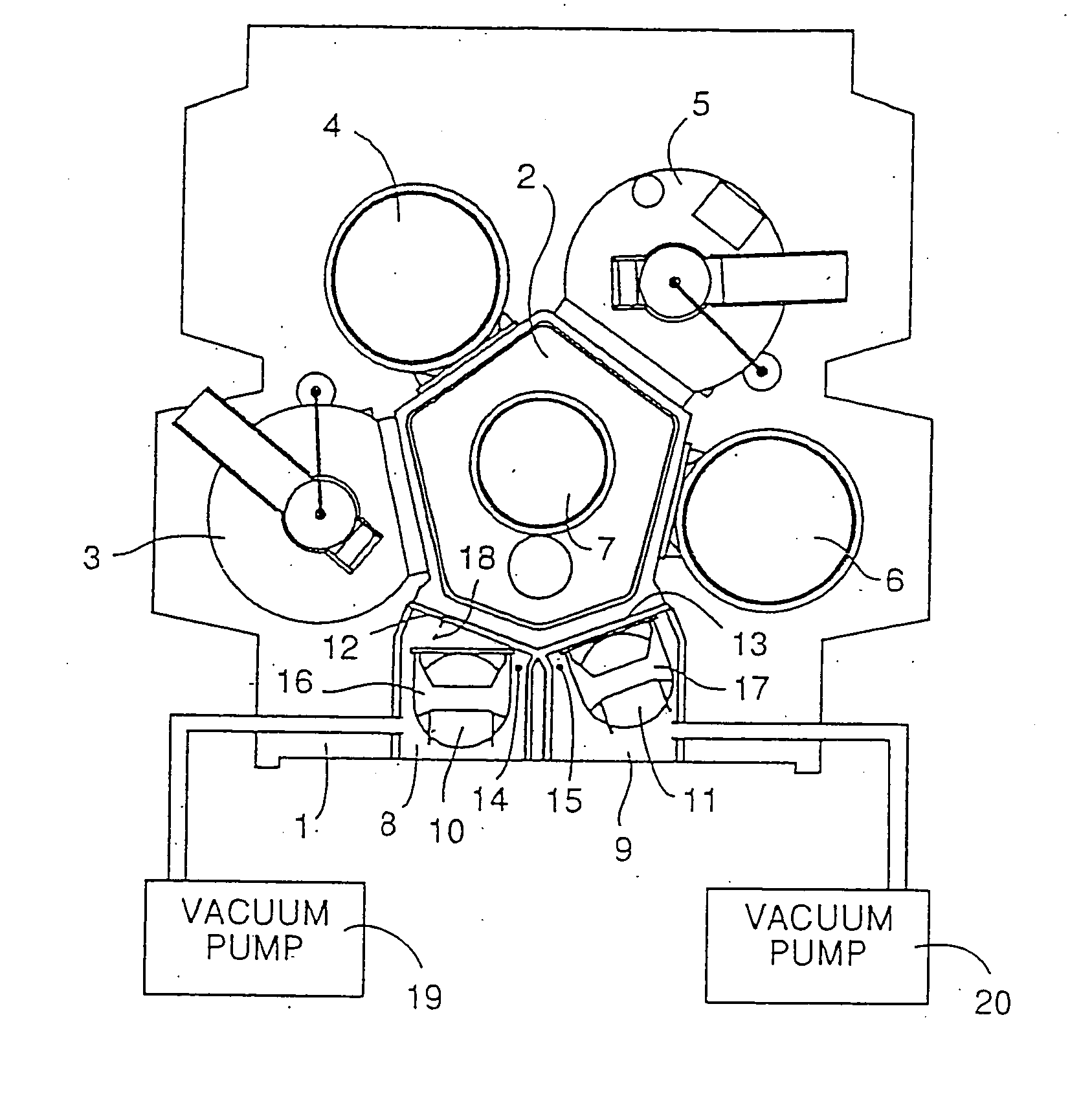
[0013] In FIG. 1, a top view of semiconductor processing equipment 1 is shown. Semiconductor processing equipment 1 may be used, for example, for etching wafers.

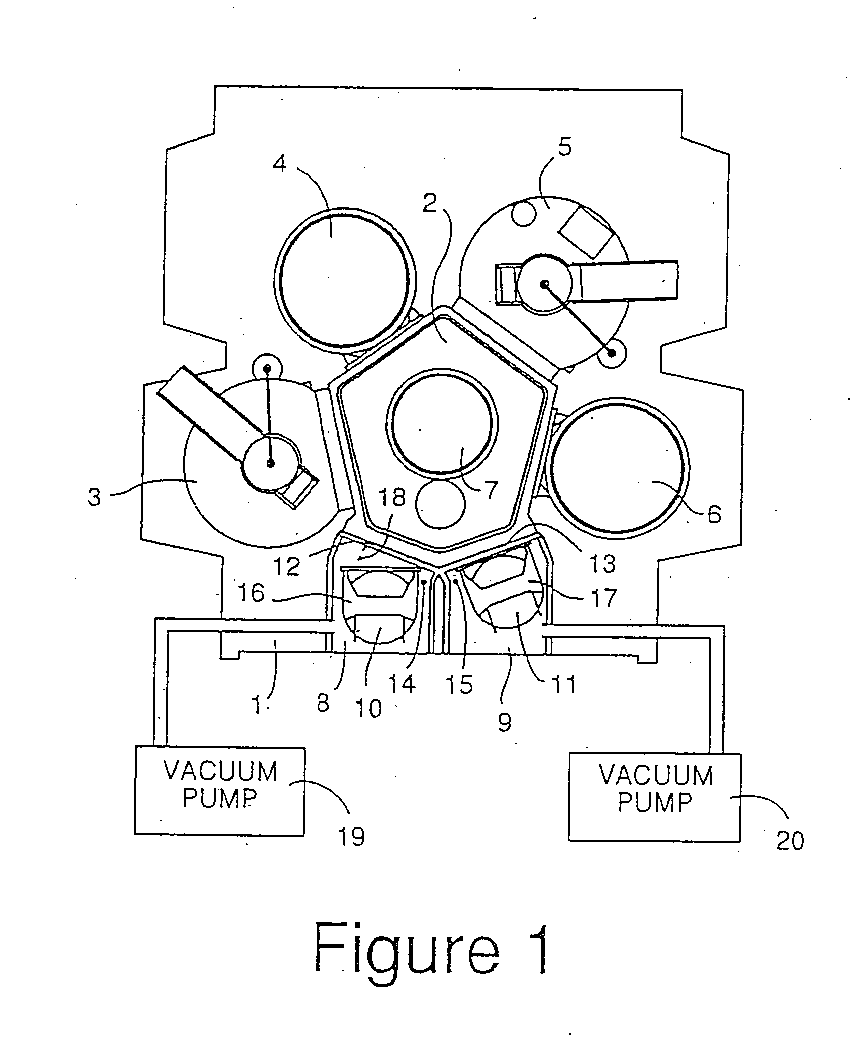
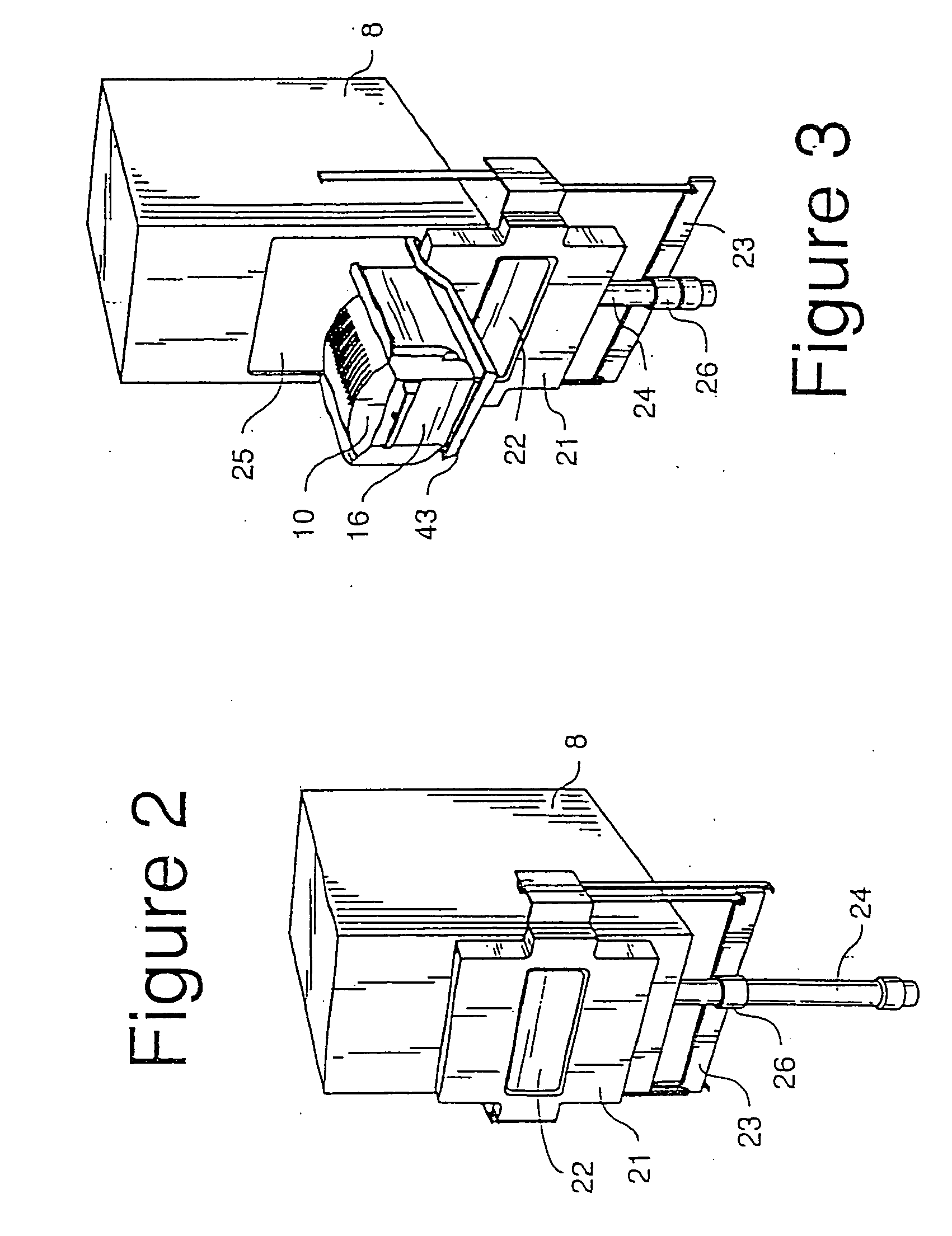
[0014] Semiconductor processing equipment1, includes, for example, a processing chamber 3, a processing chamber 4, a processing chamber 5 and a processing chamber 6. A central chamber 2 may be used to temporarily store wafers on robotic equipment 7 when wafers are being moved to or from various of the processing chambers.

[0015] Semiconductor processing equipment 1 also includes dual cassette load locks. In chamber 8, a wafer cassette 16 holds wafers 10. In chamber 9, a wafer cassette 17 holds wafers 11. Wafer tray 17 pivots around a pivot point 15. When wafers 11 from tray 17 are accessed by semiconductor processing equipment 1 for processing, wafer tray 17 is flush against a gate 13, as shown, and easily accessed by robotic equipment 7 for transportation into central chamber 2. When wafer tray 17 is ready to be removed fr...


PUM


Abstract

A workpiece loading interface is included within a workpiece processing system which processes workpieces, typically wafers, in a vacuum. The workpiece loading interface includes two separate chambers. Each chamber may be separately pumped down. Thus, while a first cassette of wafers, from a first chamber is being accessed, a second cassette of wafers may be loaded in the second chamber and the second chamber pumped down. Each chamber is designed to minimize intrusion to a clean room. Thus a door to each chamber has a mechanism which, when opening the door, first moves the door slightly away from an opening in the chamber and then the door is moved down parallel to the chamber. After the door is opened, a cassette of wafers is lowered through the opening in a motion much like a drawbridge. The cassette may be pivoted within the chamber when the position from which wafers are accessed from the cassette differs from the position from which the cassette is lowered out of the chamber.

Description

BACKGROUND [0001] The present invention relates to a front end loading interface used in the loading of workpieces in semiconductor processing equipment. [0002] Semiconductor processing equipment often has a plurality of chambers in which processing occurs. Arm assemblies or other robotic devices are generally used to move workpieces, generally wafers from a wafer queuing station to various chambers for processing. When the processing is finished the wafer is returned to the queuing station. For an example of prior art processing equipment, see U.S. Pat. No. 4,715,921 issued to Maher, et al. for a Ouad Processor. [0003] Semiconductor processing is typically done in a vacuum. Therefore, a wafer queuing station into which is placed a cassette of wafers to be processed must be pumped down before the wafers may be accessed. This significantly increases the time the semiconductor processing equipment is idle while waiting for a cassette of processed wafers to be exchanged for a cassette ...

Claims


Application Information

Patent Timeline
Patent Type & Authority Applications(United States)
IPC IPC(8): H01L21/677H01L21/02B65G49/05B65G49/07B65G65/00H01L21/205H01L21/285H01L21/302H01L21/3065
CPCH01L21/67201H01L21/67754H01L21/67766Y10S414/14H01L21/67778Y10S414/137Y10S414/139H01L21/67772H01L21/30
Inventor TOSHIMA, MASATO M.SALZMAN, PHIL M.MURDOCH, STEVEN C.WANG, CHENGSTENHOLM, MARK A.HOWARD, JAMESHALL, LEONARD
Owner TOSHIMA MASATO M
Why Eureka
Try Eureka