
Cleaning (de-poisining) PEMFC electrodes from strongly adsorbed species on the catalyst surface

a catalyst surface and electrode technology, applied in the field of fuel cells, can solve the problems of affecting the performance of pemfc, affecting the fc, and various impurities at levels

Inactive Publication Date: 2006-11-09
LOS ALAMOS NATIONAL SECURITY
View PDF1 Cites 25 Cited by
  • Summary
  • Abstract
  • Description
  • Claims
  • Application Information

AI Technical Summary

Benefits of technology

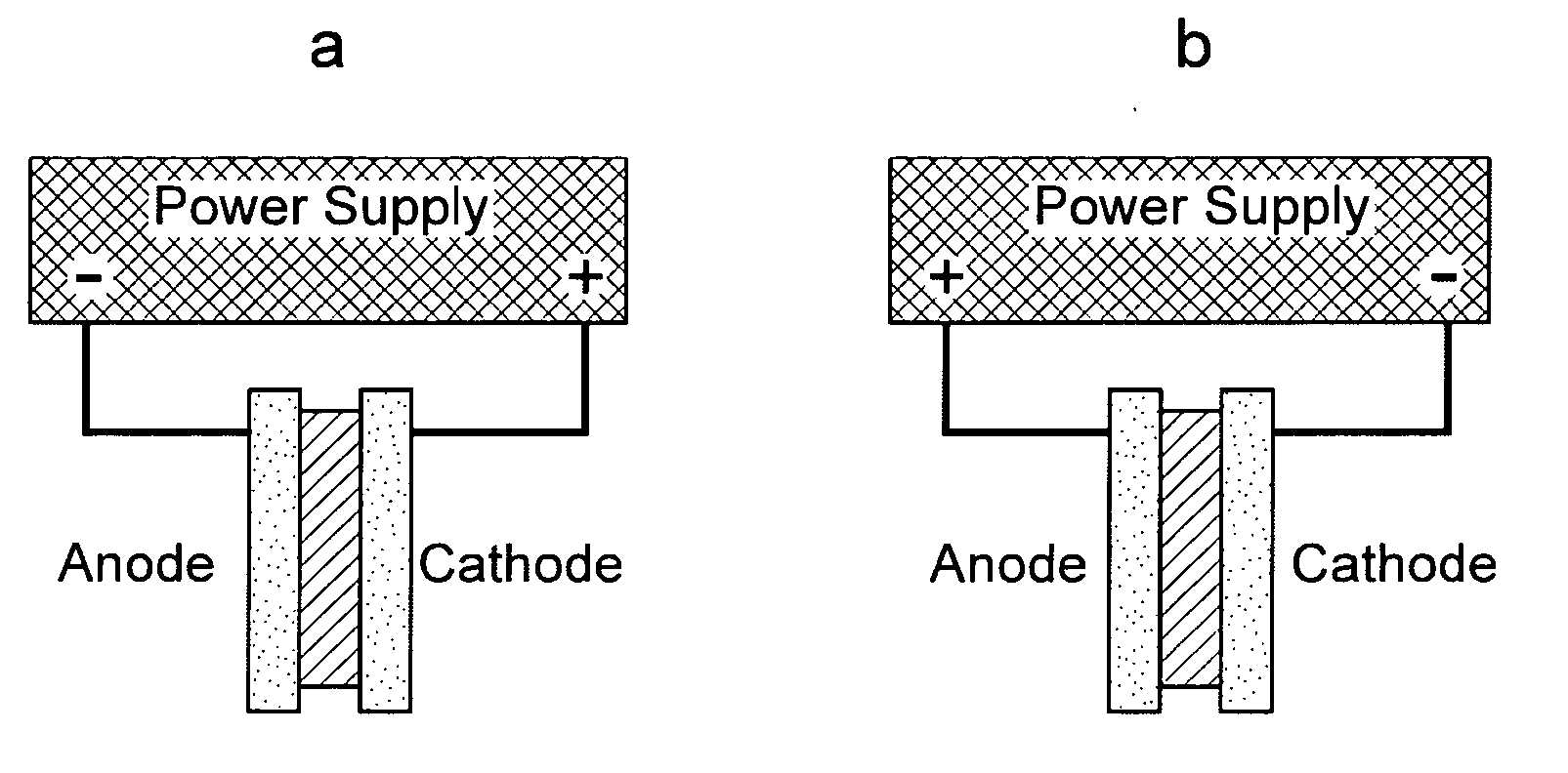
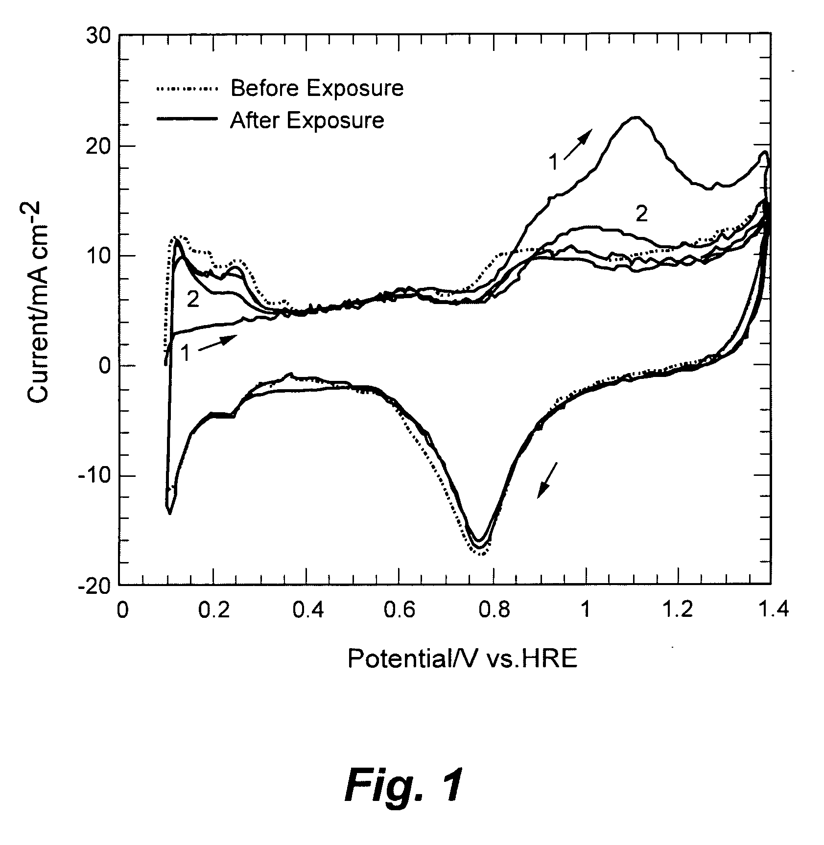
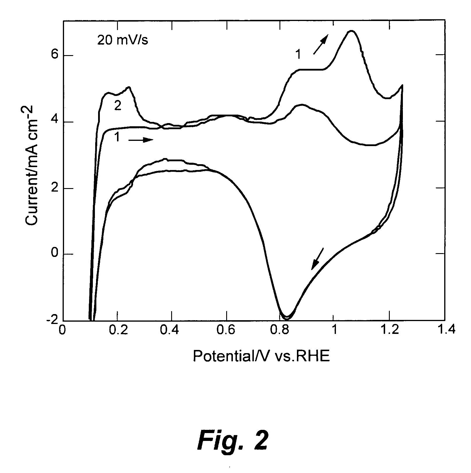
The present invention is a method for cleaning the electrochemical catalyst of fuel cell electrodes using a low-power supply. The method involves applying a power pulse to remove chemisorbed chemical species from the electrodes, which improves the performance of the fuel cell.

Problems solved by technology

Therefore, PEMFC performance may be strongly affected by the presence of contaminants in the fuel and in the air stream.
For instance, reformation of hydrocarbon fuels such as methane or gasoline, besides H2, may produce various impurities at levels that can be detrimental to fuel cell (FC) operation.
Other impurities may be present as contaminants in the ambient air injected to the cathode during FC operation.
However, performing CV involves interrupting fuel cell operation for a considerable amount of time (at least 1 hour).
In addition the electrode being probed has to be purged with an inert gas (N2 or Ar), which is time consuming and requiring a potentiostat, which is a rather expensive instrument.

Method used


Image

  • Cleaning (de-poisining) PEMFC electrodes from strongly adsorbed species on the catalyst surface
  • Cleaning (de-poisining) PEMFC electrodes from strongly adsorbed species on the catalyst surface
  • Cleaning (de-poisining) PEMFC electrodes from strongly adsorbed species on the catalyst surface

Examples


example 1

Cleaning a Fuel Cell Cathode Contaminated with SO2

Poisoning with SO2

[0024]FIG. 4 shows the cell current density as a function of time for a fuel cell experiment in which the cell operated at constant voltage (0.6 V). Initially the cell cathode ran on impurity-free air for 20 minutes and then operated with air contaminated with 10 ppm of SO2 for 20 minutes. The negative effect of the impurity on performance was observed as soon as the SO2 injection started and it is indicated by the sudden decrease in the current, which eventually dropped below 20% of the original value. Once the SO2 injection was interrupted, the cell ran on neat air again for about 24 minutes. A slow and small recovery was observed. Numerous SO2 poisoning tests indicate that the recovery does not improve even if the cell continued operating on clean air for several days.

Fuel Cell Cathode Cleaning

[0025] The fuel cell was momentarily turned off before the cleaning was started. Then, the positive terminal of the...

example 2

Cleaning a FC Anode Contaminated with H2S

Anode Poisoning with H2S and Cleaning Electrode with H2 Flow Interruption

[0026]FIG. 6 shows a similar experiment to example 1, but this time for an anode whose hydrogen fuel supply was contaminated with 2 ppm of H2S. Initially the cell ran on impurity-free hydrogen for 40 minutes, showing steady performance. Then it was exposed to H2S-contaminated hydrogen for 30 minutes. The cell current dropped considerably to 56% of its initial value. As expected, after stopping the injection of H2S the anode experienced insignificant recovery when the cell resumed operation on neat hydrogen again. Prior to applying the power pulse to the FC, the H2 gas flow was completely interrupted while the air flow was significantly reduced for about 10 minutes. This allowed the existing hydrogen at the anode to be consumed, leaving only the chemisorbed electroactive species on the Pt catalyst to be electro-oxidized by the external power pulse. Thus, prior consumpt...


PUM

PropertyMeasurementUnit
fixed voltageaaaaaaaaaa
timeaaaaaaaaaa
voltageaaaaaaaaaa

Abstract

A method for cleaning the electrochemical catalyst of fuel cell electrodes that is performed by applying a power pulse, using a low-power supply, across the fuel cell electrodes. The power pulse removes chemisorbed chemical species from the electrochemical catalyst of the electrodes.

Description

RELATED APPLICATIONS [0001] This application claims the benefit of provisional application No. 60 / 679,038 filed on May 6, 2005, titled “Cleaning (De-poisoning) PEMFC Electrodes from Strongly Adsorbed Species on the Catalyst Surface”.STATEMENT REGARDING FEDERAL RIGHTS [0002] This invention was made with government support under Contract No. W-7450-ENG-36 awarded by the U.S. Department of Energy. The government has certain rights in the invention.FIELD OF THE INVENTION [0003] The present invention relates generally to fuel cells, and, more particularly to a method for cleaning (de-poisoning) fuel cell electrodes from strongly adsorbed species on the catalyst surface. BACKGROUND OF THE INVENTION [0004] Proton Exchange Membranes Fuel Cells (PEMFC) are devices that generate electrical power from two complementary electrochemical reactions. Hydrogen is oxidized at the anode and oxygen is reduced at the cathode. Thus, efficient fuel cell operation relies on the availability of both the cle...

Claims


Application Information

Patent Timeline
Patent Type & Authority Applications(United States)
IPC IPC(8): C25F1/00
CPCH01M8/04223Y02E60/50H01M2008/1095H01M8/04238H01M8/04873H01M8/043
Inventor URIBE, FRANCISCO A.ROCKWARD, TOMMY Q.T.
Owner LOS ALAMOS NATIONAL SECURITY
Learn More