Device for operating gas in vacuum or low-pressure environment and for observation of the operation

a vacuum or low-pressure environment and gas-operating technology, applied in the field of gasiform operation, can solve the problems of gas leakage into the vacuum zone, aberration and resolution loss, complicated disassembly and assembly of electron microscopes, etc., and achieve the effect of convenient operation, convenient assembly and convenient assembly

Inactive Publication Date: 2006-11-09
CONTREL TECH CO LTD
View PDF4 Cites 8 Cited by
  • Summary
  • Abstract
  • Description
  • Claims
  • Application Information

AI Technical Summary

Benefits of technology

[0015] The first objective of the present invention is to provide a device for operating gas in the vacuum or low-pressure environment and for observation of the operation. The device provides the environment for observation of gas without alteration of original structure of the electron microscope.
[0016] The second objective of the present invention is to provide a device for operating gas in the vacuum or low-pressure environment and for observation of the operation. The device can control parameters of pressure of the gas more easily than the prior art to reach higher pressure.
[0018] The fourth objective of the present invention is to provide a device for operating gas in the vacuum or low-pressure environment and for observation of the operation. The device can be more easily operated and more conveniently assembled.
[0019] The foregoing objectives of the present invention are attained by the present invention, which includes a housing. The housing has a thinner part formed at a side thereof, and at least one spacer mounted therein for partitioning off its inside into a gas chamber and at least one buffer chamber outside the gas chamber. The gas chamber has two inner apertures provided on the spacer above and below the gas chamber. The housing has two outer apertures provided respectively on a top side thereof and a bottom side thereof. All of the inner and outer apertures are coaxial with one another and located on the thinner part. The housing has a pumping port for communication with the buffer chamber, and a gas inlet for communication with the gas chamber. Therefore, the device of the present invention can provide the environment for observation of the gas, being conveniently assembled and easily operated, without alteration of the original structure of the electron microscope.

Problems solved by technology

Although the aforementioned prior art can enable generation of extremely low-pressure vapor in the vapor layer, there are still some drawbacks for improvement.
However, disassembling and assembling the electron microscope is very complicated, requiring experts to do it well, and is very costly and subject to damage to electron microscope.
Heightening the specimen chamber of the electron microscope may result in alteration of the focal length of the electron beam to further cause aberration and loss of resolution.
Increasing the gas pressure inside the vapor layer will result in leakage of the gas into the vacuum zone, as shown in FIG. 13, disabling the operation of standard atmospheric pressure inside the vapor layer.
Although dramatically enhancing evacuation for the buffer layers 766 can overcome this problem, the high-speed pumping rate caused by the enhanced evacuation may result in strong turbulence, causing multiple scattering caused by the electrons impinging the gas molecules and further disabling successful imaging of the electron beam or experiment of electron diffraction.
Because the space between the pole pieces inside the electron microscope is about 1 cm high in size and treated as a gas chamber, if the gas pressure inside the environment chamber keeps increasing, the multiple scattering of the electrons will become excessive.
In addition, Gai's design concept is identical to Hui's in that it is necessary to disassemble the primary part of the electron microscope before installing the whole system including the gas chamber and the buffer layers, such that it hardly possible to mass-produce the system.
However, they all exhibit the same problem of multiple scattering of the electrons while operating the gas chamber at the standard atmospheric pressure.

Method used


Image

  • Device for operating gas in vacuum or low-pressure environment and for observation of the operation
  • Device for operating gas in vacuum or low-pressure environment and for observation of the operation
  • Device for operating gas in vacuum or low-pressure environment and for observation of the operation

Examples


Embodiment Construction

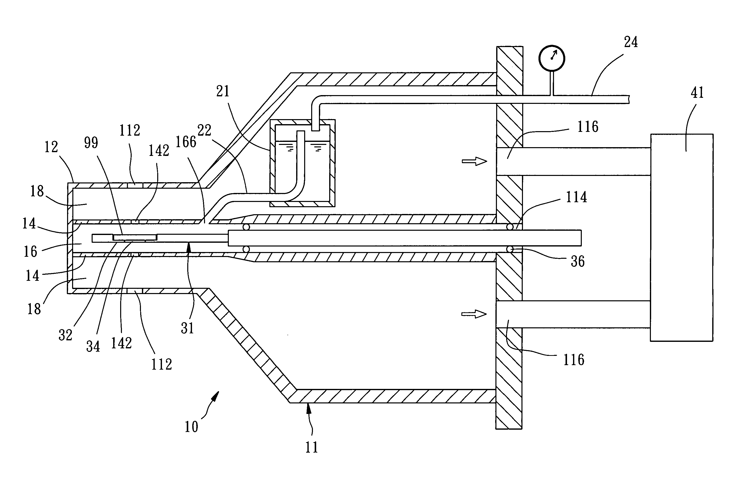
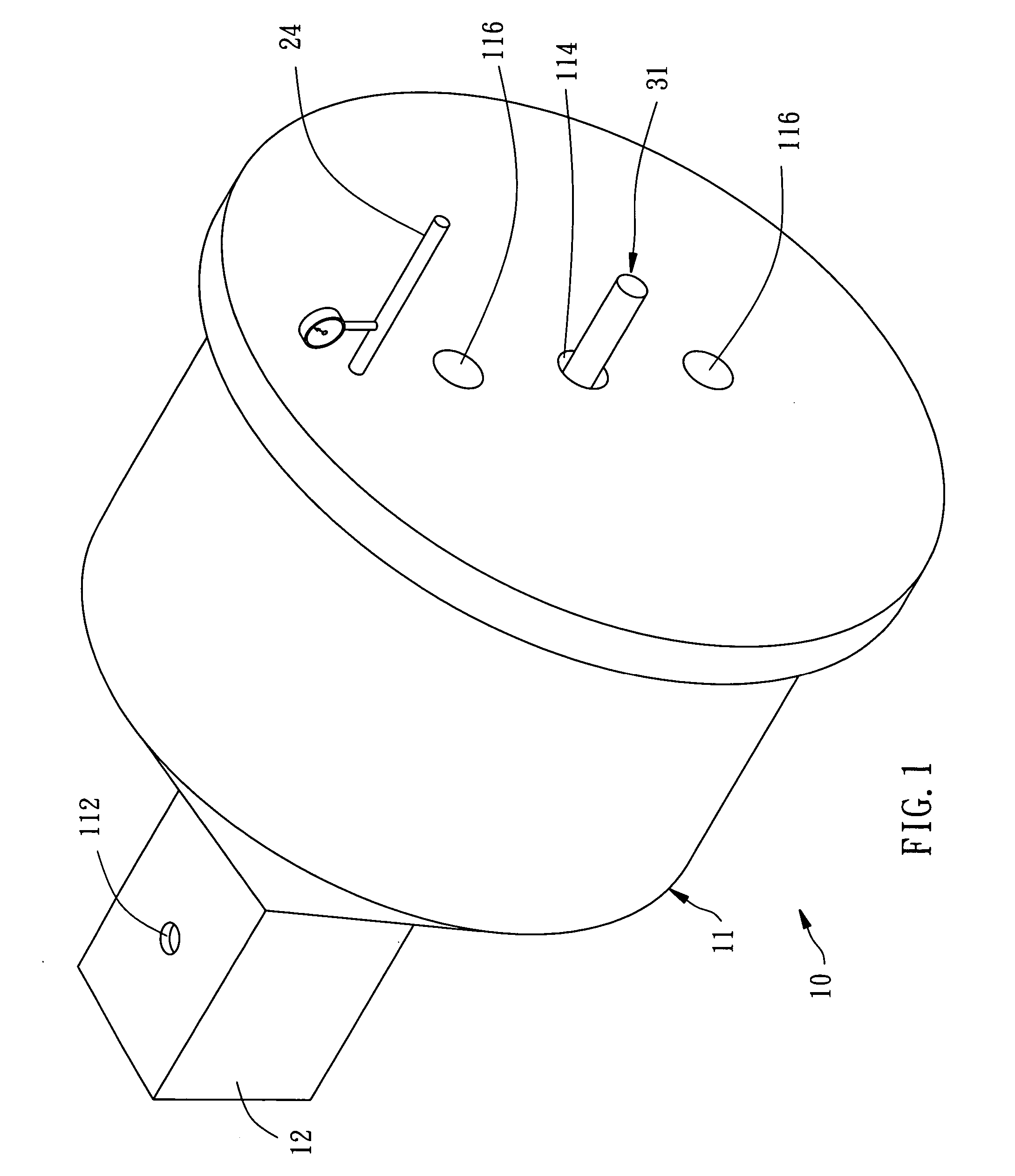
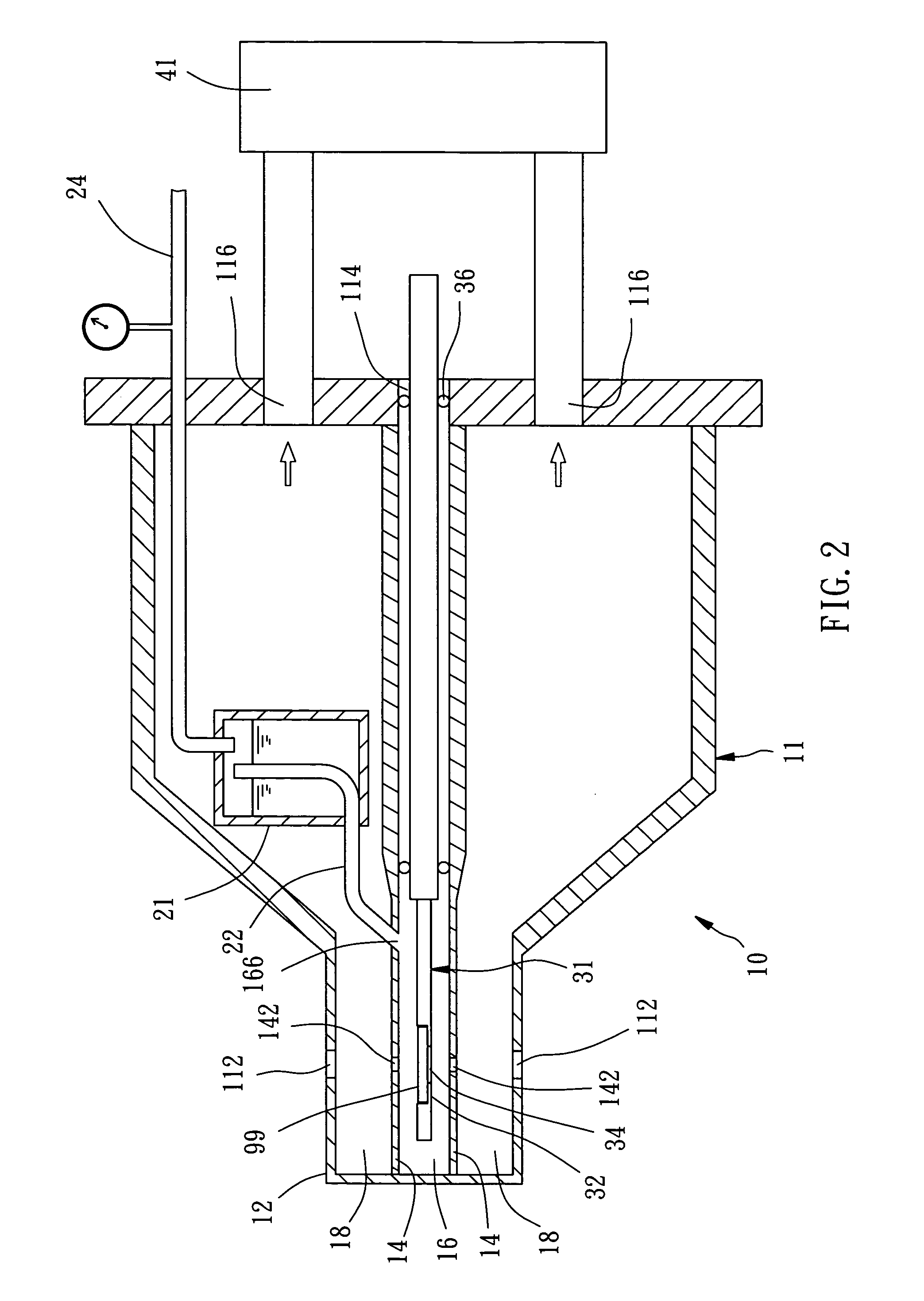
[0033] Referring to FIGS. 1-3, a device 10 for operating gas in the vacuum or low-pressure environment and for observation of the operation, constructed according to a first preferred embodiment of the present invention, is composed of a housing 11, a temperature-controllable liquid-gas container 21, a specimen holder 31, and a pumping device 41, in cooperation with an electron microscope 91. The electron microscope 91 has a specimen chamber 92 therein, two pole pieces 96 mounted respectively at upper and lower sides of the specimen chamber 92, and an insertion port 94 located at a side of the specimen chamber 92 for inserting the device 10.

[0034] The housing 11 includes a thinner part 12 formed at a side thereof, and a plurality of spacers 14 mounted in an interior space within the housing 11. The thinner part has a thickness that is substantially smaller than the distance between the two pole pieces 96 of the specimen chamber 92. The distance between the pole pieces 96 is general...


PUM

PropertyMeasurementUnit
Diameteraaaaaaaaaa
Diameteraaaaaaaaaa
Diameteraaaaaaaaaa

Abstract

A device for operating gas in the vacuum or low-pressure environment and for observation of the operation includes a housing. The housing has a thinner part formed at a side thereof, and at least one spacer mounted therein for partitioning off its inside into a gas chamber and at least one buffer chamber outside the gas chamber. The gas chamber has two inner apertures provided on the spacers above and below the gas chamber. The housing has two outer apertures provided respectively on a top side thereof and a bottom side thereof. All of the inner and outer apertures are coaxial with one another and located on the thinner part. The housing has a pumping port for communication with the buffer chamber, and a gas inlet for communication with the gas chamber.

Description

BACKGROUND OF THE INVENTION [0001] 1. Field of the Invention [0002] The present invention relates generally to the technology of operating gasiform substance in the vacuum or low-pressure environment, and more particularly, to a device for operating gas in the vacuum or low-pressure environment and for observation of the operation. [0003] 2. Description of the Related Art [0004] As far as the technology of microscopic observation is concerned, it is known that a user can employ an electron microscope with its high-power magnification to do scientific research of nanometer substances. [0005] A conventional electron microscope works by utilizing an electron beam to probe the substance. It is necessary to utilize the accelerated electron beam by high voltage and to focus the electron beam by using the electromagnetic lenses to do the microscopic observation in a vacuum environment. As shown in FIG. 11, an electron microscope 61 includes a vacuum specimen chamber 62 for receiving a spec...

Claims


Application Information

Patent Timeline
IPC IPC(8): H01J37/18
CPCH01J2237/2002H01J37/20G01N23/2251
Inventor CHAO, CHIH-YUHSIEH, WEN-JIUNN
Owner CONTREL TECH CO LTD
Why Eureka
Try Eureka