Eureka AIR delivers breakthrough ideas for toughest innovation challenges, trusted by R&D personnel around the world.

Technique for tuning an ion implanter system

Active Publication Date: 2006-11-09
VARIAN SEMICON EQUIP ASSOC INC
View PDF11 Cites 7 Cited by
  • Summary
  • Abstract
  • Description
  • Claims
  • Application Information

AI Technical Summary

Benefits of technology

[0009] A technique for tuning an ion implanter system is disclosed. In one particular exemplary embodiment, the technique may be realized as a method for tuning an ion implanter system having multiple beam-line elements. The method may comprise establishing on

Problems solved by technology

However, due to a number of deficiencies, existing methods for tuning an ion implanter system often fail to achieve a consistent ion beam output in an efficient manner.
Since the previously recorded single set of beam-line element settings often cannot reproduce a desired ion beam condition, the ion implanter system has to be re-tuned for every wafer batch, which is quite time-consuming for reasons described below.
However, identical ion beam currents do not necessarily guarantee identical ion beam conditions.
As a result, single-parameter approaches that rely solely on ion beam current can lead to inconsistent ion beam geometries.
The one-element-at-a-time approach is effectively a blind search in a vast data universe and therefore is very time-consuming.
Since a small change in one beam-line element often results in a shift of an optimal point in another, the one-element-at-a-time approach can easily mistune the ion implanter system.

Method used


Image

  • Technique for tuning an ion implanter system
  • Technique for tuning an ion implanter system
  • Technique for tuning an ion implanter system

Examples


Embodiment Construction

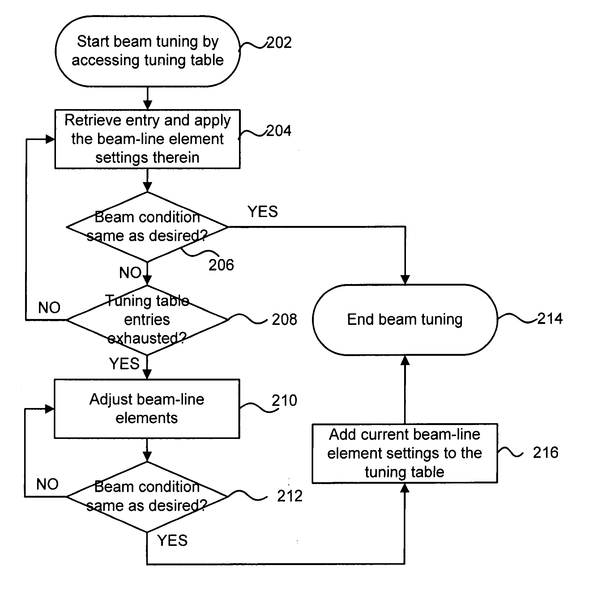
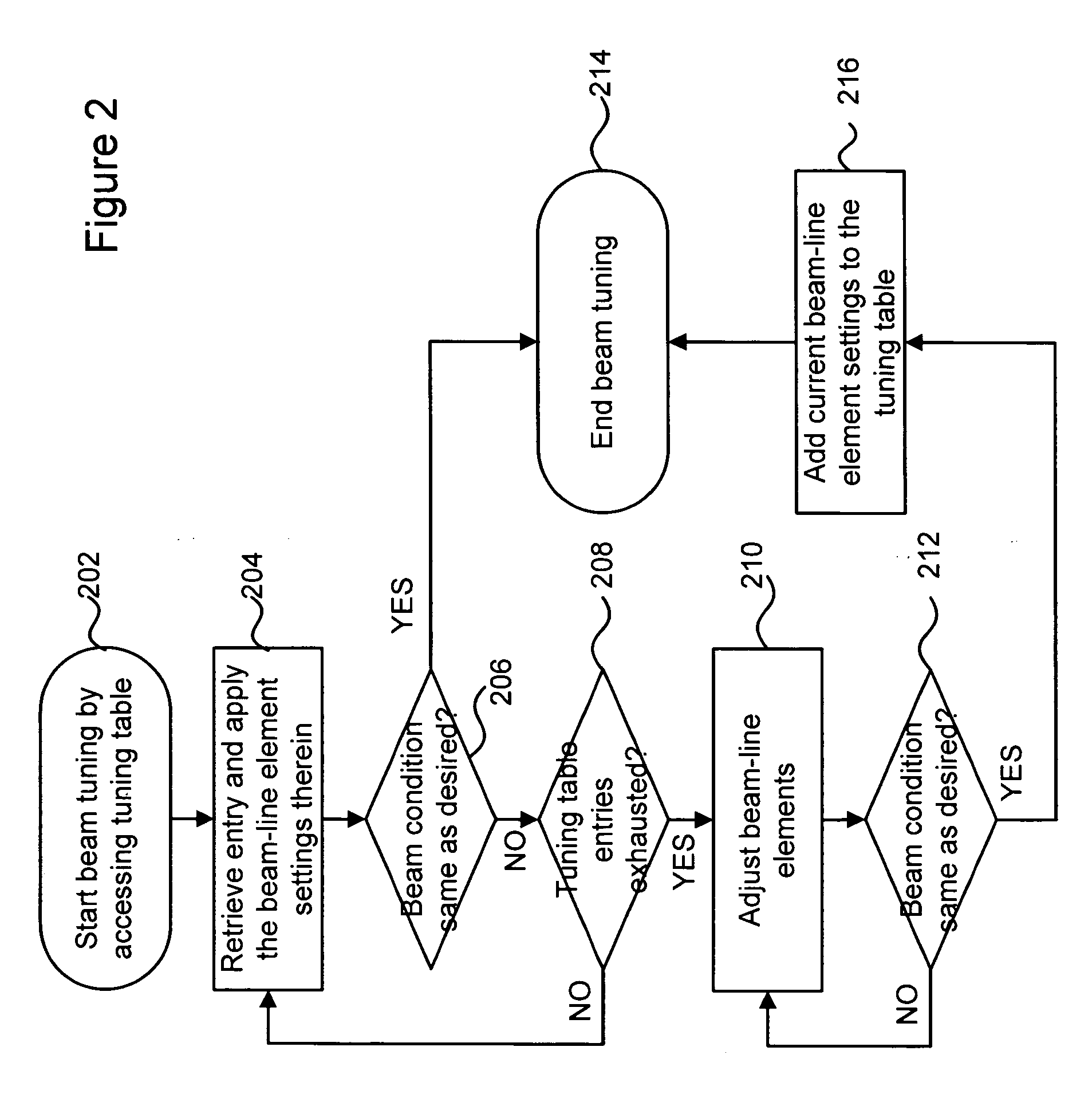
[0023] Embodiments of the present disclosure are directed to a technique for tuning an ion implanter system having multiple beam-line elements. An improved tuning method is introduced to adjust the multiple beam-line elements in a coordinated manner based on a tuning table and / or an optic model. The tuning table may be implemented with a self-learning function that keeps accumulating ion beam setup data to improve the tuning efficiency. The optic model may provide predictive control for the tuning process in order to expedite a search for desired ion beam conditions. Furthermore, embodiments of the improved tuning method typically rely on multiple parameters as criteria or for guidance in tuning the ion beam, thereby ensuring a more consistent ion beam output than the prior art single-parameter approach.

[0024] Referring to FIG. 2, there is shown a flow chart illustrating an exemplary method for tuning an ion implanter system in accordance with an embodiment of the present disclosur...


PUM


Abstract

A technique for tuning an ion implanter system is disclosed. In one particular exemplary embodiment, the technique may be realized as a method for tuning an ion implanter system having multiple beam-line elements. The method may comprise establishing one or more relationships among the multiple beam-line elements. The method may also comprise adjusting the multiple beam-line elements in a coordinated manner, based at least in part on the one or more established relationships, to produce a desired beam output.

Description

FIELD OF THE DISCLOSURE [0001] The present disclosure relates generally to semiconductor equipment and, more particularly, to a technique for tuning an ion implanter system. BACKGROUND OF THE DISCLOSURE [0002] Ion implantation is a process of depositing chemical species into a substrate by direct bombardment of the substrate with high-energy ions. In semiconductor fabrication, ion implanters are used primarily for doping processes that alter the type and level of conductivity of target materials. A precise doping profile in an integrated circuit (IC) substrate and its thin-film structure is often crucial for the IC performance. To achieve a desired doping profile, one or more ion species may be implanted in different doses and at different energy levels. A specification of the ion species, doses and energies is referred to as an ion implantation recipe. [0003]FIG. 1 depicts a prior art ion implanter system 100. As is typical for most ion implanter systems, the system 100 is housed i...

Claims


Application Information

Patent Timeline
IPC IPC(8): H01J37/302H01J37/317
CPCH01J37/3023H01J2237/31703H01J2237/30411H01J37/3171
Inventor CHANG, SHENGWUOLSON, JOSEPH C.BRENNAN, DAMIAN
Owner VARIAN SEMICON EQUIP ASSOC INC
Why Eureka
Eureka Blog
Learn More