Plug-in hybrid vehicle with fast energy storage

a hybrid vehicle and energy storage technology, applied in the direction of electric propulsion mounting, battery/fuel cell control arrangement, battery/cell propulsion, etc., can solve the problems of deep cycling, reduced battery life, and inability to realize the full potential of conventional hybrid propulsion, so as to reduce the number of charge discharge cycles, fast energy storage reduces the life-cycle cost of batteries, and the effect of increasing battery li

Inactive Publication Date: 2006-11-09
AFS TRINITY POWER CORP
View PDF15 Cites 209 Cited by
  • Summary
  • Abstract
  • Description
  • Claims
  • Application Information

AI Technical Summary

Benefits of technology

[0036] One advantage of the invention is a reduced number of charge discharge cycles of the battery with correspondingly increased battery life. This is accomplished by using a fast energy storage system that has a cycle life exceeding battery cycle life by at least 10× and sizing the fast energy storage system to source or sink brief, frequent pulses and provide most or all of the V2G ancillary services.
[0037] A second advantage of the invention is that fast energy storage reduces the life-cycle cost of a battery. Without fast energy storage, the battery will experience a large number of shallow cycles and occasional high current pulses when the battery is at a low state of charge. The invention reduces the number of shallow charge cycles that the battery would experience by as much as 90%-100% and protects the battery from high current pulses. In particular, the fast energy storage system protects the battery from the deleterious effects of high rate discharge while at a low state of charge. By doi...

Problems solved by technology

The main problem with existing conventional hybrids is that the full potential of conventional hybrid propulsion is not realized due to limited all-electric travel range.
The main problems with existing plug-in hybrid vehicles are the cost of batteries and limited battery life.
Deep cycling reduces battery life.
The plug-in hybrid battery is much larger and proportionately more expensive than the battery in a conventional hybrid vehicle.
Therefore, the cost penalty assoc...

Method used


Image

  • Plug-in hybrid vehicle with fast energy storage
  • Plug-in hybrid vehicle with fast energy storage
  • Plug-in hybrid vehicle with fast energy storage

Examples


Embodiment Construction

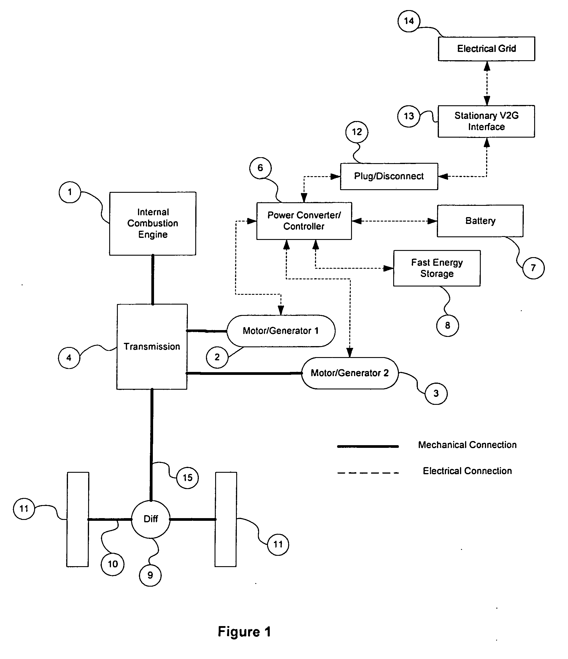
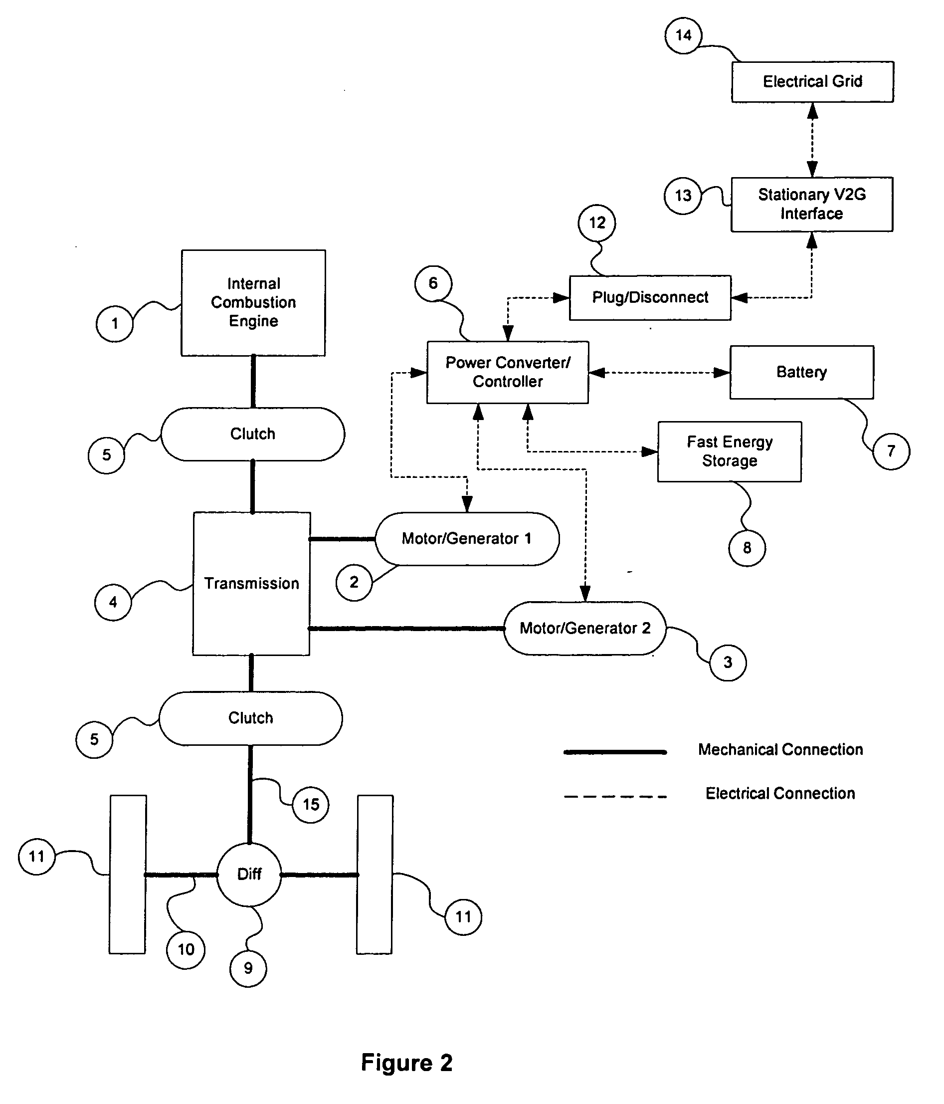
[0085] Referring to FIG. 1, a preferred embodiment of apparatus is disclosed. The invention comprises an engine 1 connected to a transmission 4. The engine 1 may be connected through a clutch or may be connected through fixed gears or shafting. A first motor / generator 2 is connected to the shaft either on the engine 1 or the transmission 4 side of the engine / transmission interface. The transmission 4 transfers power from the engine 1 and first motor / generator 2 through the transmission 4 to the driveshaft 15, differential 9, and then the axle 10 and the wheels 11. A second motor / generator 3 is connected to the transmission 4 at a point in the transmission 4 closer to the output. The drivetrain may use zero, one, two, or three clutches to selectively disengage the engine 1 or an individual motor / generator 2, 3.

[0086] The drivetrain comprises the driveshaft 15 and differential 9, which both may be part of the transmission 4 or separate from it, and the axle 10 or split shaft.

[0087] ...


PUM


Abstract

This invention relates to plug-in hybrid propulsion systems where the energy storage element of the hybrid drive train may be charged with externally supplied electricity as well as energy from the engine or regenerative braking. The invention is a plug-in hybrid system with a fast energy storage and delivery system. In a preferred embodiment the invention comprises a fuel powered engine, a battery, a fast energy storage system, power converters, controllers, drive motors, an electrical distribution system, and a drive train. Additionally, the invention relates to plug-in hybrids that provide services to the electrical utility when the vehicle is connected to the utility grid.

Description

FIELD OF INVENTION [0001] This invention relates to plug-in hybrid propulsion systems for cars, trucks, and buses where the energy storage element of the hybrid drive train may be charged with externally supplied electricity as well as energy from the engine or regenerative braking. [0002] In particular, the invention relates to plug-in hybrids that can provide services to the electrical utility when the vehicle is connected to the utility grid. RELATED ART [0003] Existing products commonly found in the marketplace include conventional hybrid vehicles such as the Toyota Prius, Honda Insight, and Ford Escape Hybrid. More closely related to the present invention are prototype Daimler Chrysler Sprinter plug-in hybrid vans. [0004] The main problem with existing conventional hybrids is that the full potential of conventional hybrid propulsion is not realized due to limited all-electric travel range. This problem is addressed by increasing the energy storage capacity of the vehicle to all...

Claims


Application Information

Patent Timeline
IPC IPC(8): H04B1/20
CPCB60K1/02Y02T10/648B60K6/46B60K6/48B60K6/52B60K6/54B60L11/123B60L11/126B60L11/14B60L11/1816B60L11/1824B60L11/1842B60L15/007B60L2260/28Y02T10/6217Y02T10/6221Y02T10/6265Y02T10/6269Y02T10/6278Y02T10/646Y02T10/7005Y02T10/7022Y02T10/7077Y02T90/121Y02T90/128Y02T90/14Y02T90/163Y04S10/126Y02E60/721B60K6/30Y02T10/7072B60L53/14B60L50/15B60L50/61B60L50/62B60L50/16B60L53/30B60L55/00B60L58/20Y02E60/00Y02T10/62Y02T10/64Y02T10/70Y02T90/12B60K6/28H04B1/20B60K6/20Y02T90/16
Inventor BENDER, DONALD ARTHURDESHMANE, ATULMEANS, ANDREW ELDON
Owner AFS TRINITY POWER CORP
Why Eureka
Try Eureka