
Apparatus and methods for altering a characteristic of a light-emitting device

a technology of light-emitting devices and apparatus, which is applied in the field of apparatus and methods for altering the characteristic of light-emitting devices, can solve the problems of not being wavelength-selective devices, reflectors, and complex laser cavities, and achieve the effect of large clear aperture and high damage threshold

Active Publication Date: 2006-11-09
NECSEL INTPROP
View PDF33 Cites 4 Cited by
  • Summary
  • Abstract
  • Description
  • Claims
  • Application Information

AI Technical Summary

Benefits of technology

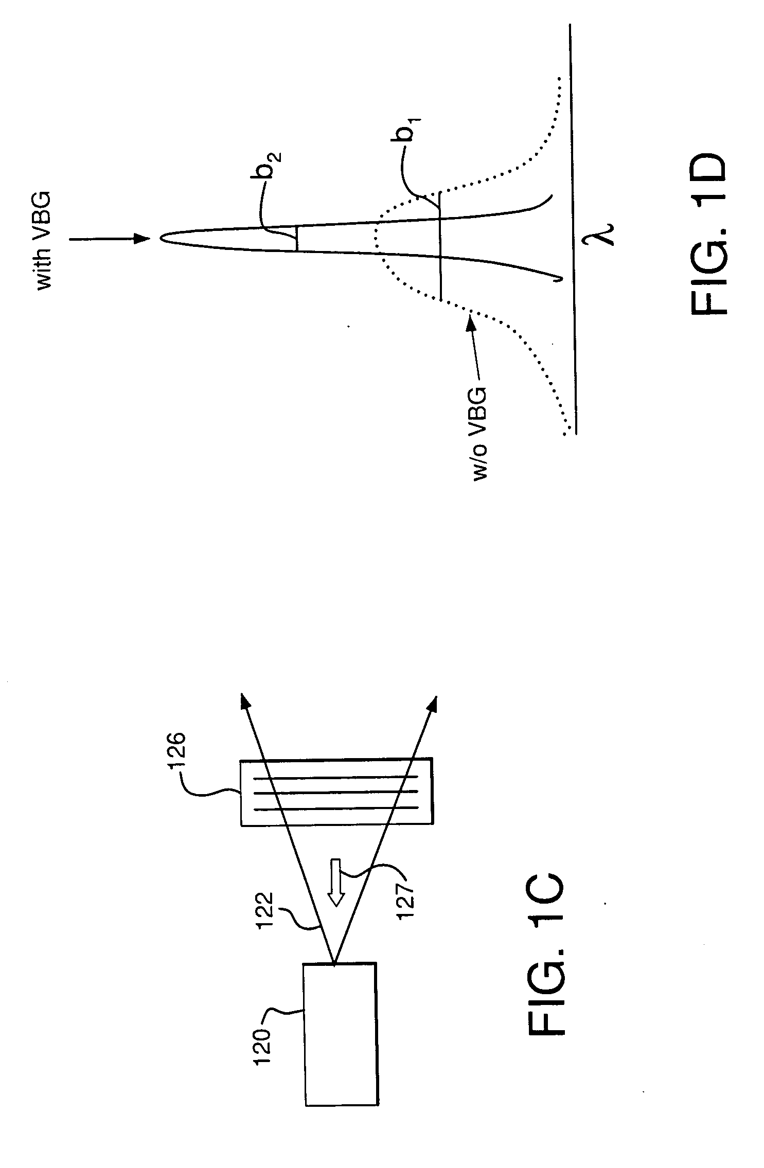
VBG elements enable stable, single-mode operation and improved output characteristics, including spectral narrowing, spatial mode selection, and temporal profile shaping, enhancing the performance of light-emitting devices by providing a high damage threshold and flexible design options.

Problems solved by technology

Laser cavities or resonators, however complex, typically include two or more mirrors or other reflecting devices that form a closed optical path for rays traveling in a certain direction.
Such reflectors, however, were not wavelength-selective devices.
This approach suffered from instabilities stemming from the non-selective nature of the feedback.
Although successful in a laboratory, this approach results in rather bulky devices, which are difficult to align and to maintain in the field.
However, to the inventors' knowledge, neither the possibility of using a VBG element for extra-cavity narrow-band feedback nor a practical device for achieving narrow-band operation of a single-transverse mode semiconductor laser diodes have been disclosed previously.
To the inventors' knowledge, there are currently no devices in the market that employ volume Bragg grating elements for conditioning of laser characteristics, nor are there any successful practical devices in the market that use any of the above-mentioned approaches to improve the output characteristics of arrays of lasers.

Method used


Image

  • Apparatus and methods for altering a characteristic of a light-emitting device
  • Apparatus and methods for altering a characteristic of a light-emitting device
  • Apparatus and methods for altering a characteristic of a light-emitting device

Examples


Embodiment Construction

Overview

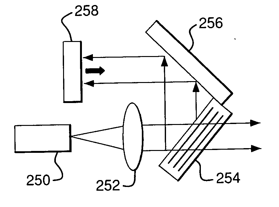
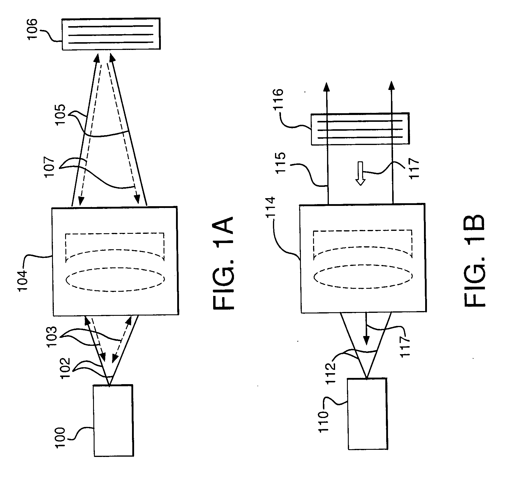
[0042] There are at least two general approaches to using VBG elements for conditioning a characteristic of a light emitting device: a) using a VBG that is outside of the laser cavity (extra-cavity); and b) using a VBG that is inside laser cavity (intra-cavity).

[0043] As discussed above, a laser resonator may be viewed as a closed optical path formed between mirrors and / or other light-reflecting elements. Such a closed optical path is typically a condition that is necessary for lasing to occur. For this reason, it is desirable that any intra-cavity element added to the resonator does not alter this condition, lest it impede light generation via stimulated emission. By contrast to intra-cavity elements, extra-cavity elements may be free from such a constraint. Furthermore, the efficiency of light generation typically depends nonlinearly on single-pass cavity loss. Thus, it is also desirable that any intra-cavity element used for laser output conditioning have as little los...


PUM


Abstract

Apparatus and methods for altering one or more spectral, spatial, or temporal characteristics of a light-emitting device are disclosed. Generally, such apparatus may include a volume Bragg grating (VBG) element that receives input light generated by a light-emitting device, conditions one or more characteristics of the input light, and causes the light-emitting device to generate light having the one or more characteristics of the conditioned light.

Description

CROSS-REFERENCE TO RELATED APPLICATIONS [0001] This application is a division of U.S. patent application Ser. No. 10 / 884,524, filed Jul. 2, 2004, which claims benefit under 35 U.S.C. § 119(e) of provisional U.S. patent applications Ser. Nos. 60 / 484,857, filed Jul. 03, 2003, and 60 / 564,526, filed Apr. 26, 2004. The respective disclosures of each of the above-referenced patent applications are incorporated herein by reference.FIELD OF THE INVENTION [0002] The invention is related generally to light emitting devices, such as lasers, laser diodes, light-emitting diodes, super-luminescent laser diodes, etc. More specifically, the invention provides for using one or more volume Bragg grating (VBG) elements for modifying (or conditioning) one or more output characteristics of such devices. BACKGROUND OF THE INVENTION [0003] Laser cavities or resonators, however complex, typically include two or more mirrors or other reflecting devices that form a closed optical path for rays traveling in a...

Claims


Application Information

Patent Timeline
Patent Type & Authority Applications(United States)
IPC IPC(8): H01S3/081H01S3/08G02B27/09H01SH01S3/00H01S5/00H01S5/06H01S5/14H01S5/40
CPCG02B27/0944G02B19/0014H01S3/08009H01S3/08031H01S3/109H01S5/005H01S5/0654H01S5/0656H01S5/141H01S5/143H01S5/4012H01S5/405H01S5/4062H01S5/4068H01S5/4087G02B19/0057H01S3/0057H01S3/08013
Inventor VOLODIN, BORIS LEONIDOVICHBAN, VLADIMIR SINISA
Owner NECSEL INTPROP
Learn More