Composite faucet

Inactive Publication Date: 2006-11-16
WAYS TECHN CORP
View PDF13 Cites 19 Cited by
  • Summary
  • Abstract
  • Description
  • Claims
  • Application Information

AI Technical Summary

Benefits of technology

[0006] The primary purpose of the present invention is to provide a composite faucet essentially comprised of a body including metal components of cold waterway, hot waterway, water inlet, water outlet, and valve chamber. The body allows both of hot and cold water flowing in the metallic waterway. Whereas metallic material yields excellent thermal withstanding and duration properties, it is ideal in the production of duration faucet to prevent water quality from being contaminated by the dissolved chemical substances when the plastic material contacts hot water. The body already coated with the refractory material is placed in a mold to be packaged with a plastic layer by means of pouring and injection to produce a composite faucet. Sine the body is coated with the refractory material, the heat from the hot water will not b

Problems solved by technology

During the process, both of the speed and acceptability of mass production are affected due to difficulties in locating the core shell.
Furthermore, the body so molded by casting requires further grinding and polishing processes that consume lost of time, money and labor.
Furthermore, residual metallic powders after grinding and polishing processes create serious environmental problem.
Hot water brings serious thermal impact upon the plastic material when the hot water direct contacts the plastic

Method used


Image

  • Composite faucet
  • Composite faucet
  • Composite faucet

Examples


Example

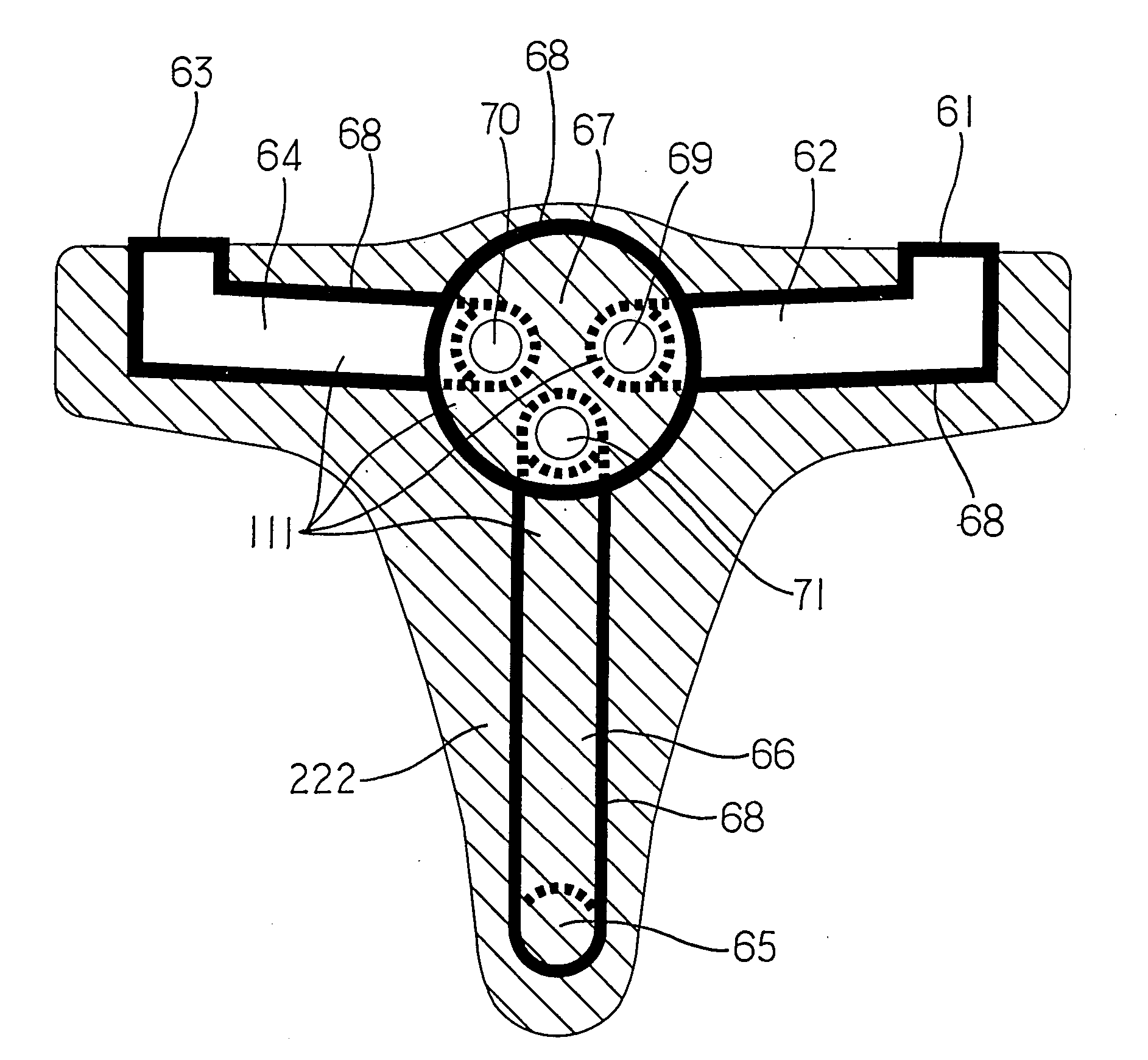
[0011] Referring to FIG. 4 for a preferred embodiment of the present invention, a composite faucet is comprised of a body111 coated with a refractory material 68 and a package layer 222 of plastic material injection molded. The body 111 includes multiple metallic components connected to one another, respectively, a cold waterway 62, a hot waterway 64, a water outlet 66, and a valve chamber 67 (to accommodate a water flow regulating valve). Wherein, one end each of the cold waterway 62, the hot waterway 64, and the water outlet 66 is connected through the valve chamber 67. A cold water inlet 61 of the cold waterway 62, a hot water outlet 63 of the hot waterway 64, and the water outlet 66 respectively form an opening 65 to keep water flowing through in the composite faucet. The body 111 coated with the refractory material 68 is placed in a mold to be covered up with the package layer 222 by means of plastic injection. Accordingly, the composite faucet of the present invention is compr...


PUM


Abstract

A composite faucet includes a body coated with refractory material, the body directly contacting with water is made of metallic alloys; the body already coated with refractory material is further covered with a plastic material by injection for easier fabrication.

Description

BACKGROUND OF THE INVENTION [0001] (a) Field of the Invention [0002] The present invention is related to a composite faucet, and more particularly, to one comprised of internal and external parts to allow fast manufacturing process and quality composite structure. [0003] (b) Description of the Prior Art [0004] The conventional mixer valve is usually cast molded in a construction as illustrated in FIGS. 1 and 2 of the accompanying drawings. Thought it provides water on / off, and water flow and temperature adjustment functions, its body is cast molded. Core shell is first placed at where the hollow cavity is located before injecting into the metallic liquid for the hollow waterway in the body. During the process, both of the speed and acceptability of mass production are affected due to difficulties in locating the core shell. Furthermore, the body so molded by casting requires further grinding and polishing processes that consume lost of time, money and labor. Furthermore, residual me...

Claims


Application Information

Patent Timeline
IPC IPC(8): F16K27/06E03C1/04F16K11/00F16K27/00
CPCE03C1/04F16K27/00F16K19/006F16K11/00Y10T137/7036E03C1/02
Inventor WU, SHINN-TYANCHEN, WEI-CHUAN
Owner WAYS TECHN CORP
Why Eureka
Try Eureka