Light efficient packaging configurations for LED lamps using high refractive index encapsulants

Inactive Publication Date: 2006-11-16
TASKAR NIKHIL R +3
View PDF3 Cites 143 Cited by
  • Summary
  • Abstract
  • Description
  • Claims
  • Application Information

AI Technical Summary

Benefits of technology

[0010] The present invention has applicability to any generally transparent HRI encapsulants and is particularly applicable to HRI encapsulants utilizing dispersed non-agglomerated HRI nanoparticles disposed in a transparent matrix of lower RI encapsulant. The presence of the HRI nanoparticles serves to raise the RI of the composite encapsulant to 1.7 or greater. In addition to the refractive index raising nanoparticles the composite encapsulant may also include light emitting phosphors which will further increase and / or alter the color of the light output

Problems solved by technology

The proposed LED lamp also avoids any fabrication and reliability challenges that are posed by the HRI material having lower mechanical and structural strength compared to a conventional encapsulant, which could also create problems with molding the dome-shaped lens.

Method used


Image

  • Light efficient packaging configurations for LED lamps using high refractive index encapsulants
  • Light efficient packaging configurations for LED lamps using high refractive index encapsulants
  • Light efficient packaging configurations for LED lamps using high refractive index encapsulants

Examples


embodiment

Hybrid Embodiment

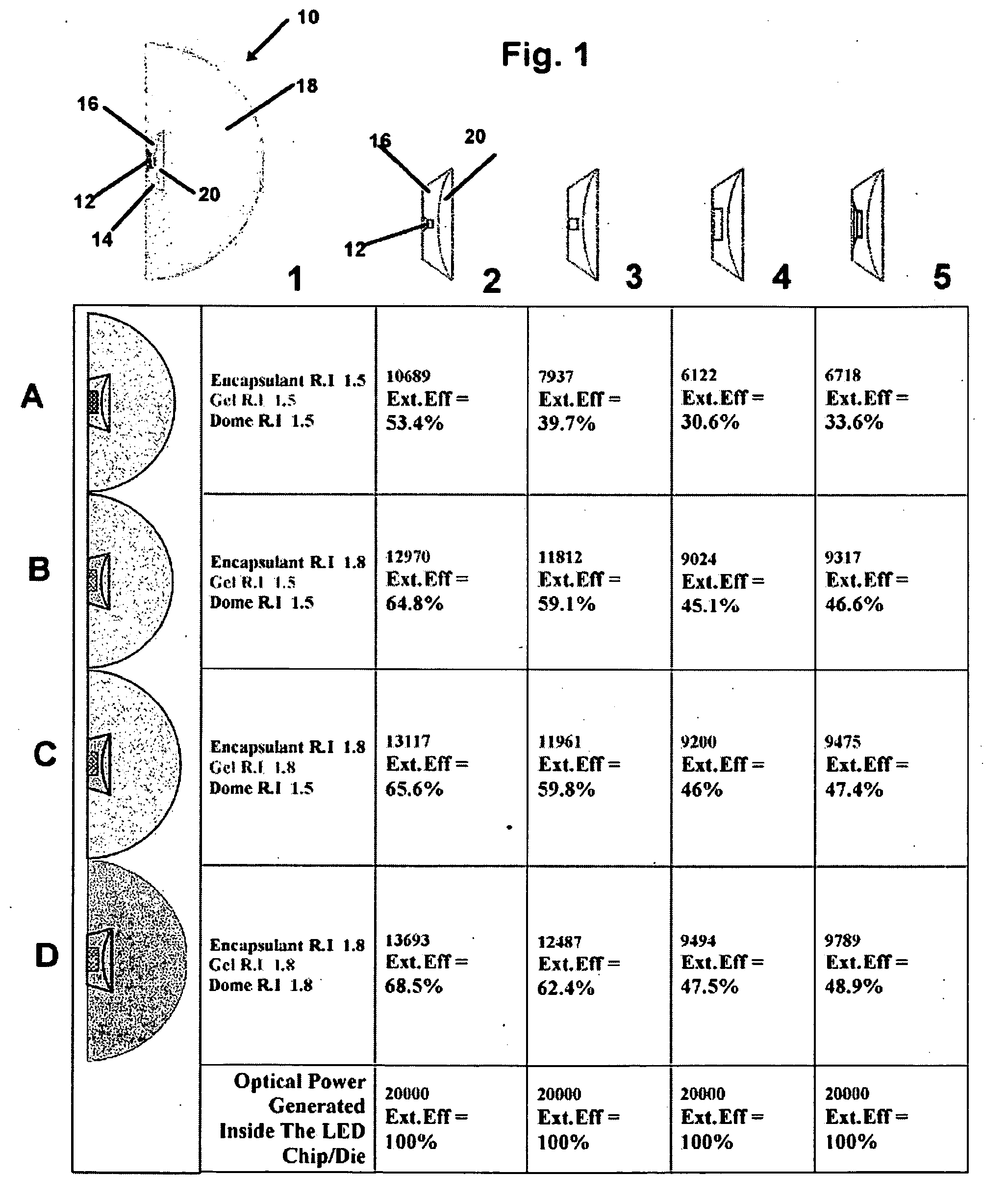
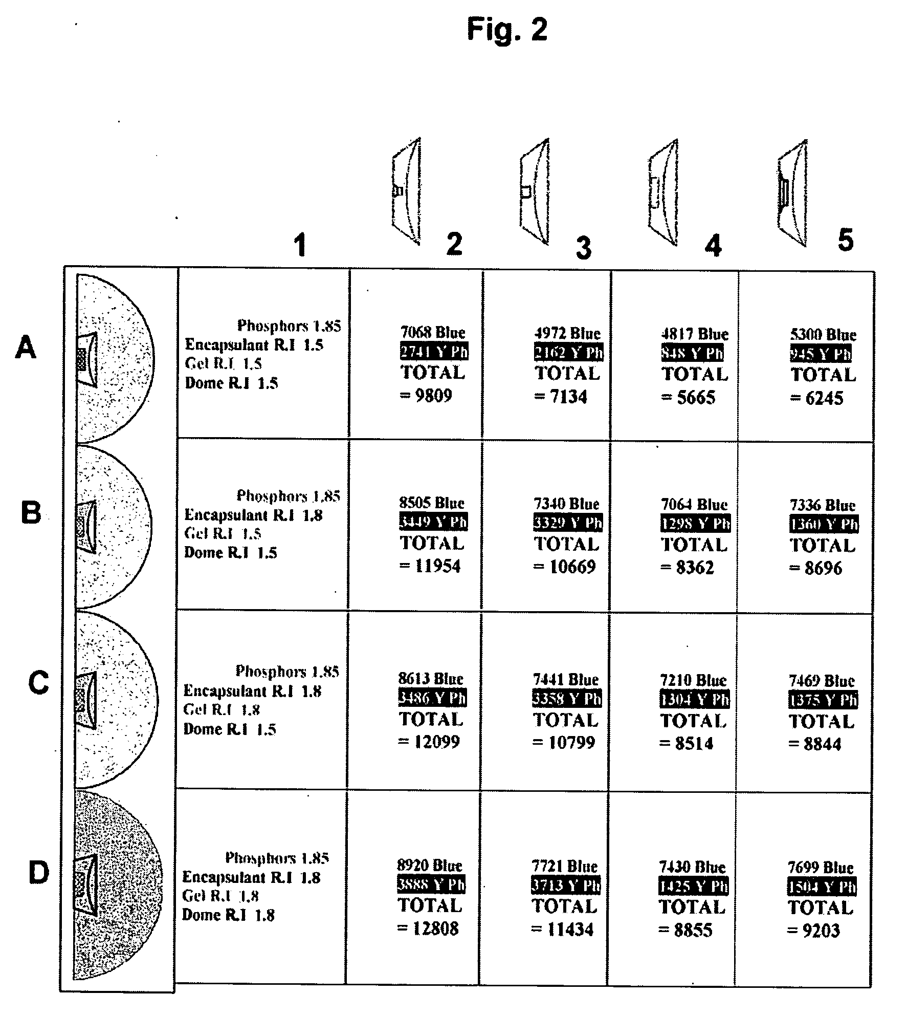
[0046]FIG. 14 illustrates a hybrid embodiment of the present invention in a which a “mini-dome”142 is disposed at the center of the concave lens 144 of the Top-Emitting SMD device as discussed above in FIGS. 11-13. The diameter (“footprint”) of the mini-dome 142 is between 100 to 1000 microns and is typically on the order dimension of the die / chip 146. The height of the mini-dome 142 is such that it does not protrude above the rim of the package (thus maintaining its form-factor) and is typically on the order of several 100 microns.

[0047] The table of FIG. 14 illustrates various configurations of LED die / chip 146 shown in rows A-C with various sizes of mini-domes 142 shown in columns 3-5. Column 1 lists the dimensions of the mini-dome: FP=footprint (diameter), R=radius of curvature of the spherical mini-dome / position of center of curvature of the mini-dome above bottom of the package, H=height of the mini-dome above the concave lens, the light output (LEE or WPE) a...


PUM


Abstract

Light efficient packaging configurations for LED lamps using high refractive index encapsulants. The packaging configurations including dome (bullet) shaped LED's, SMD (surface mount device) LED's and a hybrid LED type, including a dome mounted within a SMD package. In another embodiment used with SMD LED devices a relatively small semi-hemispherical “blob” of HRI encapsulant surrounds the LED chip with the remainder of the SMD cavity filled with conventional encapsulant. The packaging configurations increase the LED's light emission efficiency at a reasonable cost and in a commercially viable manner, by maximizing the light efficiency while minimizing the amount of high refractive index encapsulant used.

Description

REFERENCE TO RELATED APPLICATIONS [0001] This application is a continuation in part of PCT application PCT / US2004 / 029201 which in turn claims the priority of U.S. Provisional patent application Ser. No. 60 / 501,147 filed Sep. 8, 2003 and U.S. Provisional patent application Ser. No. 60 / 524,529 filed Nov. 24, 2003.BACKGROUND OF THE INVENTION [0002] This invention relates to Light Emitting devices (LED's) and configurations suitable for increasing their light emission efficiency at a reasonable cost and in a commercially viable manner. More specifically this application relates to LED lamps using high refractive index encapsulants in various packaging configurations including dome (bullet) shaped, Top-Emitting SMD (surface mount device) and a hybrid type, including a dome mounted within a SMD package. [0003] Typically, a LED lamp with a dome-shaped lens has a higher optical efficiency or Light Extraction Efficiency (LEE) than one without a dome. Hence, domed LED's have a higher Wall Plu...

Claims


Application Information

Patent Timeline
Patent Type & Authority Applications(United States)
IPC IPC(8): H01L33/00H01L33/50H01L33/54H01L33/56H01L33/58H01L33/60H05B
CPCF21V5/04F21W2131/103F21Y2101/02H01L33/60H01L33/54H01L33/56H01L33/58H01L33/501F21Y2115/10F21V5/10
Inventor TASKAR, NIKHIL R.CHABRA, VIPINDORMAN, DONALDHERKO, SAMUEL P.
Owner TASKAR NIKHIL R
Why Eureka
Try Eureka