High temperature seal and methods of use

a high-temperature seal and seal technology, applied in the field of seals, can solve the problems of limited time, large vibration in the combustible of gas turbines during operation, etc., and achieve the effects of increasing the lifetime of the seal, high spring load, and high wear resistan

Inactive Publication Date: 2006-11-16
ANSALDO ENERGIA IP UK LTD
View PDF9 Cites 47 Cited by
  • Summary
  • Abstract
  • Description
  • Claims
  • Application Information

AI Technical Summary

Benefits of technology

[0014] A seal according to a second exemplary embodiment comprises a first and second component, the first component being shaped in an arch with the outer ends of this arch being in sealing contact with component surfaces. The second component comprises one part, the ends of the second component being attached to opposite ends of the inner side of the arched first component. The first component comprises a first material having a high thermal, oxidation, and wear resistance, and the second component comprises a second material different from the first material and having a high spring load maintenance.
[0015] A seal according to a third exemplary embodiment comprises a first and second component, the first component having a planar or trough-like shape, and the second component of the seal having an arch shape that is attached to the centre of the first component. (This shape of seal is frequently referred to as a “K-seal”.) As in the first and second exemplary embodiments, the first component comprises a first material having a high thermal, oxidation, and wear resistance, and the second component comprises a second material different from the first material and having a high spring load maintenance.
[0017] The material of the second component is particularly optimised to maintain a high spring-load over a long time duration. That material does not necessarily have a high wear or thermal resistance. The spring-loaded component allows the use of the seal in an environment exposed to vibrations or other relative movements of adjacent components, with which the seal is in sealing contact.
[0018] The lifetime of the seal is increased due to the individual materials, which are optimally chosen for the functions of the individual components of the seal.
[0025] In a particular embodiment of the invention, the first component having an essentially planar shape has a slight trough shape that is preferably placed in the center of the essentially planar component. The component's overall shape remains essentially planar (as opposed to having a “bowl shape”). This shape allows thermal expansions of the first component such that the quality of sealing contacts to adjacent components do not diminish.
[0028] A cooling of the seal, the surrounding area, and the adjacent components reduces the thermal load on the seal and further improves the spring load maintenance of the second component. High spring load maintenance and thermal resistance are two characteristics that are difficult to achieve by using only one material. However, as the spring load maintenance is a function of temperature, a reduction of the thermal load increases the ability to maintain a spring over a longer time period.

Problems solved by technology

Large vibrations occur in combustors for gas turbines during operation and in particular during operation at low emission levels.
A further problem encountered in the design of such seals is the limited time, for which materials maintain a spring load during exposure to elevated temperatures.

Method used


Image

  • High temperature seal and methods of use
  • High temperature seal and methods of use
  • High temperature seal and methods of use

Examples


Embodiment Construction

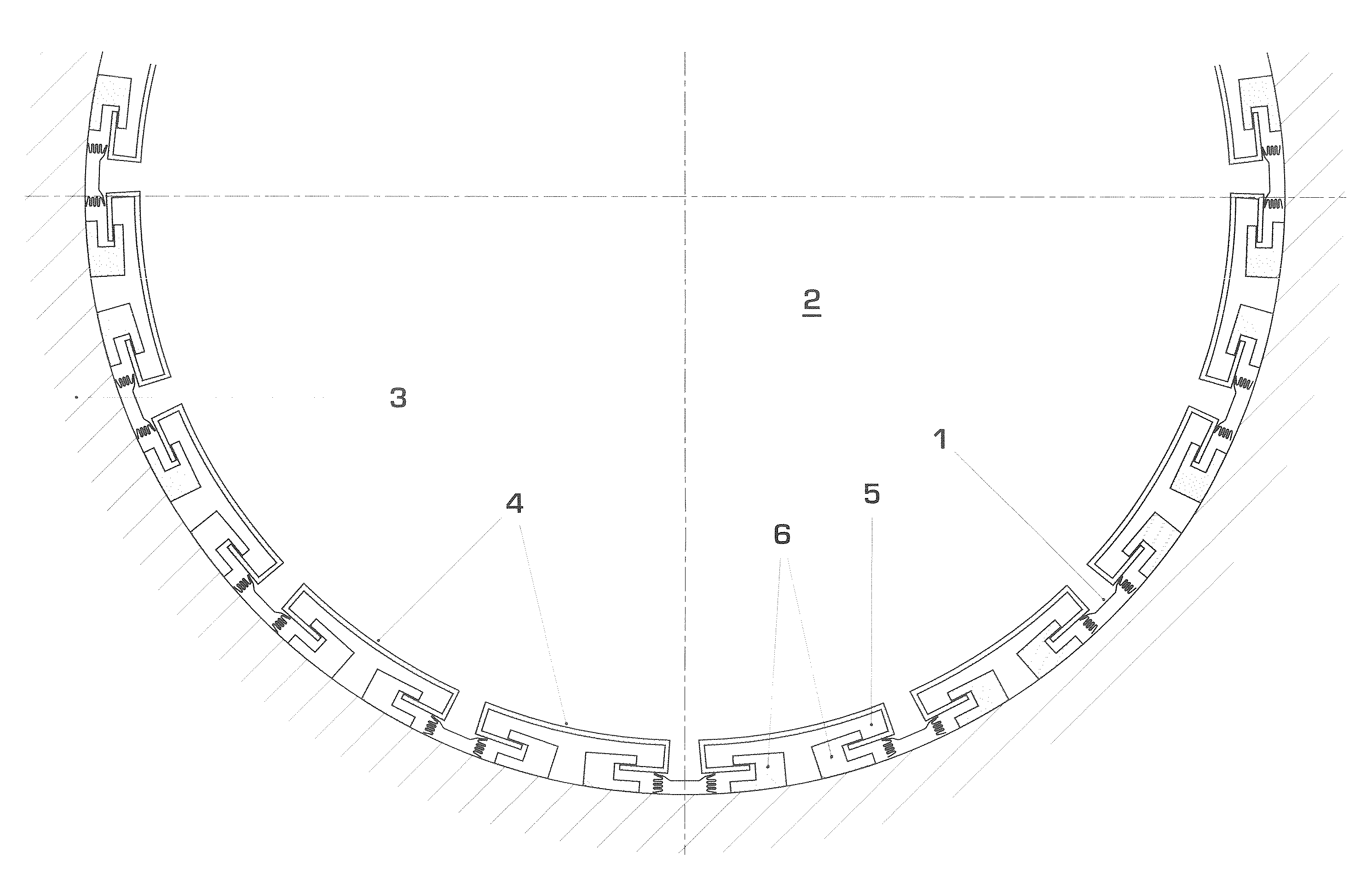
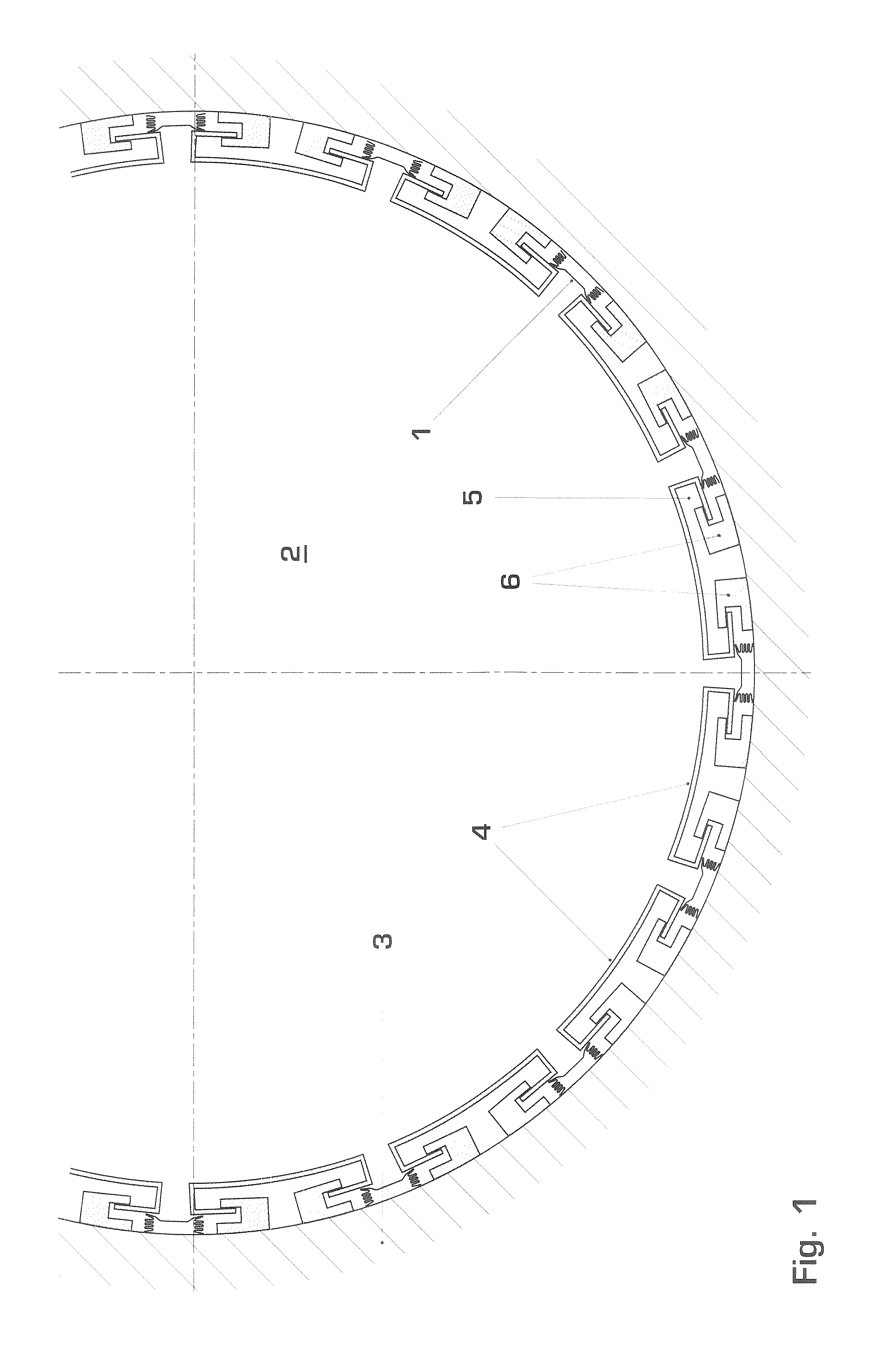
[0038] The seal according to the invention is applicable to the sealing between any two components, where one of the component is exposed to high temperatures, for example up to 1400° C. in a combustor for a gas turbine. Other applications of this seal are in the space industry, for example for nozzle seals.

[0039] A cross-section of a specific embodiment of the invention is shown in FIG. 1. The seal 1 according to the invention is applied to a combustor of a gas turbine. A combustor casing wall 3 having a circular cross-section encloses the combustor chamber 2. The combustor casing wall 3 is lined with a series of circumferentially arranged liner segments 4, which protect the combustor casing wall 3 from the high temperatures of the gas in the combustor chamber 2. Temperatures reach up to 1400° C.

[0040] (The seal is equally applicable to combustors having other shapes, for example annular shapes.)

[0041] The liner segments 4 have a slightly curved shape in accordance with the curv...


PUM


Abstract

A seal (1) includes a first component (7) and second component (9), the first component including a first material having a high thermal and oxidation and wear resistance, and the second component (9) including a second material that is different from the first material and has a high spring load maintenance. The seal (1) is applied to a combustion chamber for a gas turbine, where the first component (7) extends between the casing wall of the combustion chamber and adjacent liner segments (4). The spring load of the second component (9) provides a seal also in the case of vibrations in a combustion chamber. The lifetime of the seal (1) is increased due to the individual materials, which are optimally chosen for the functions of high thermal and wear resistance and spring load maintenance respectively. The seal is further applied to the sealing between adjacent stationary blade platforms in gas turbines.

Description

[0001] This application is a Continuation of, and claims priority under 35 U.S.C. § 120 to, International application number PCT / EP2004 / 052267, filed 22 Sep. 2004, and claims priority under 35 U.S.C. § 119 to European application number 03103664.3, filed 2 Oct. 2003, the entireties of which are incorporated by reference herein. BACKGROUND OF THE INVENTION [0002] 1. Field of the Invention [0003] The invention pertains to a seal with high temperature and high wear resistance and to the particular application of the seal in a combustor for a gas turbine or between blade platforms in a gas turbine. [0004] 2. Brief Description of the Related Art [0005] Seals applied in high temperature environments such as in combustors for gas turbines, in industrial gas turbine technology, steam turbine technology, and aerospace technology are required to withstand high temperatures for a given time duration. In many cases, due to vibrations present in such systems, they are also required to provide a ...

Claims


Application Information

Patent Timeline
Patent Type & Authority Applications(United States)
IPC IPC(8): F16J15/02F16J15/08F23R3/00
CPCF16J15/0887F23R2900/00012F23R3/002F23M2900/05005F16J15/02F16J15/08
Inventor AMOS, PETER GRAHAMBOSTON, IAN WILLIAMCORNETT, KENNET W.HURTER, JONASMORE, DOMINICK GREGORYSTEMANN, MARKUSZAGORSKIY, ALEXANDER
Owner ANSALDO ENERGIA IP UK LTD
Why Eureka
Try Eureka