Electrolyte, production process therefor, electrolyte membrane, production process therefor, catalyst layer and fuel cell

a technology of electrolyte and catalyst layer, which is applied in the direction of cell components, final product manufacturing, sustainable manufacturing/processing, etc., can solve the problems of low mechanical strength at high temperatures, problems to be resolved, and poor oxidation resistance of fluorocarbon-type electrolyte, etc., to achieve high ion exchange capacity, high proton conductivity, and high oxidation resistance

Inactive Publication Date: 2013-05-14
TOYOTA CENT RES & DEV LAB INC +1
View PDF15 Cites 0 Cited by
  • Summary
  • Abstract
  • Description
  • Claims
  • Application Information

AI Technical Summary

Benefits of technology

[0023]It is an object of the present invention to provide an electrolyte that has high conductivity and is difficult to swell or dissolve in water and a production process therefor, and an electrolyte membrane, a production process therefor, a catalyst layer and a fuel cell using the electrolyte.
[0024]It is another object of the present invention to provide an electrolyte that is low-priced and has a low load to environment and a production process therefor, and an electrolyte membrane, a production process therefore, catalyst layer and a fuel cell using the electrolyte.
[0025]It is still another object of the present invention to provide an electrolyte that has high heat resistance and oxidation resistance, and has commercially sufficient gas barrier property and flexibility when it is used as a membrane and a production process therefor, and an electrolyte membrane, a production process therefor, a catalyst layer and a fuel cell using the electrolyte.
[0038]Since the electrolyte according to the present invention uses a fluorinated segment having the high ion exchange capacity for the hydrophilic segment, it has high proton conductivity and high oxidation resistance. Meanwhile, the hydrophobic segment includes the hydrocarbon segment, but in the electrolyte, since the hydrophilic segment and the hydrophobic segment are separated from each other in a micro-phase, it is difficult to oxidize the hydrocarbon segment. It is deemed that hydrogen peroxide or hydroxy radical oxidizing the membrane is present in the hydrophilic segment having water. In particular, when the hydrophilic segment and the hydrophobic segment both of which have a predetermined molecular weight or more are block copolymerized, since a microphase separation structure is apparent, there is a low possibility of attacking of hydrogen peroxide or hydroxy radical to the hydrophobic segment. Further, even if the hydrophobic segment is oxidized, since the hydrophobic segment does not include fluorine, a load to environment is small.
[0039]In addition, if the molecular weight of the hydrophobic segment is increased to a predetermined value or more, the membrane may be made insoluble. Further, if the hydrocarbon segment is used in the hydrophobic segment, the gas barrier property of the electrolyte membrane is improved. Further, in general, the electrolyte membrane that includes only the hydrocarbon polymer is hard, but if a soft fluorinated segment is used as the hydrophilic segment, flexibility may be provided to the membrane.

Problems solved by technology

Furthermore, the fluorocarbon-type electrolyte has excellent oxidation resistance but is costly.
However, in order to use the solid polymer fuel cell as a power source for vehicles, some problems to be resolved have been left.
However, the known fluorinated electrolyte membrane has a problem in that mechanical strength is low at high temperatures.
However, since the electrolyte having the high ion exchange capacity has high water content, a swelling change of the membrane is significant.
Therefore, the shape of the membrane may not be maintained or it may be dissolved in water.
However, if the fluorinated polymer is used in both segments, there are problems in that the cost is increased and a load to environment is increased.

Method used


Image

  • Electrolyte, production process therefor, electrolyte membrane, production process therefor, catalyst layer and fuel cell
  • Electrolyte, production process therefor, electrolyte membrane, production process therefor, catalyst layer and fuel cell
  • Electrolyte, production process therefor, electrolyte membrane, production process therefor, catalyst layer and fuel cell

Examples


examples 1 to 3

Comparative Example 1

1. Manufacturing of the Sample

1.1 Synthesis of the Hydrophobic Segment

1.1.1 Synthesis of OH Terminated PEES (poly(etherethersulfone))

[0233]To a 500 mL three-neck flask to which the Dean-Stark tube and the three-way cock were connected, bisphenol: 7.17 g (38.5 mmol), bis-(4-chlorophenyl)sulfone: 10 g (34.8 mmol), and K2CO3: 24.3 g (176 mmol) were added, and they were dried for 1 hour under vacuum.

[0234]Commercial dehydrated DMAc: 120 mL and toluene: 120 mL were added thereto, and heated at 100° C. for 1 hour. Subsequently, the temperature was slowly increased to 165° C., the generated water and toluene were in an azeotropic state, and water was removed along with toluene from the reaction system. In addition, after they were reacted for 7 days at 165° C., an excess amount of bisphenol: 12.9 g (69 mmol) was added, and the reaction was performed at the same temperature for 2 days. After the reaction was carried out, the precipitated inorganic salts were filtered. T...

example 1

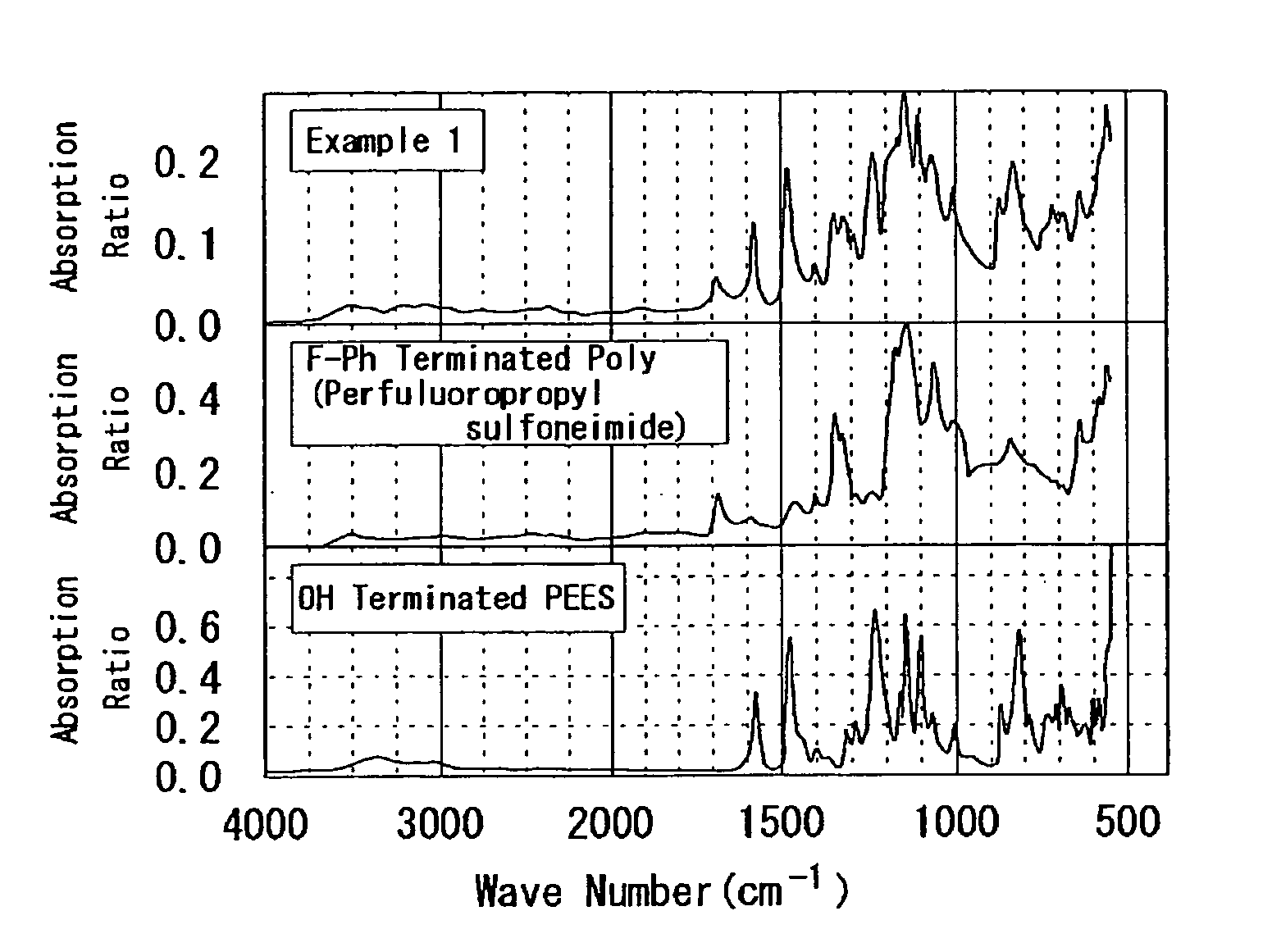
[0247]According to the following process, PEES-block-poly(perfluoropropyl sulfoneimide) was synthesized. That is, to a 100 mL two-neck recovery flask to which the Dean-Stark tube and the three-way cock were connected, OH terminated PEES (h=2.2): 0.67 g (0.64 mmoI), F-Ph terminated poly(perfluoropropyl sulfoneimide) (j=17): 0.99 g (0.19 mmol), K2CO3: 0.99 g (7.2 mmol), and 18-crown-6: 0.12 g (0.44 mmol) were added, and they were dried for 1 hour under vacuum.

[0248]Commercial dehydrated DMAc: 15 mL and toluene: 20 mL were added thereto, and heated at 100° C. for 1 hour. Subsequently, the temperature was slowly increased to 165° C., the generated water and toluene were in an azeotropic state, and water was removed along with toluene from the reaction system. In addition, after they were reacted for 14 days at 165° C., they were reprecipitated in THF and water and dried under vacuum for overnight to obtain a desired product (0.24 g). The following Formula (c.1) illustrates the synthesis...

example 2

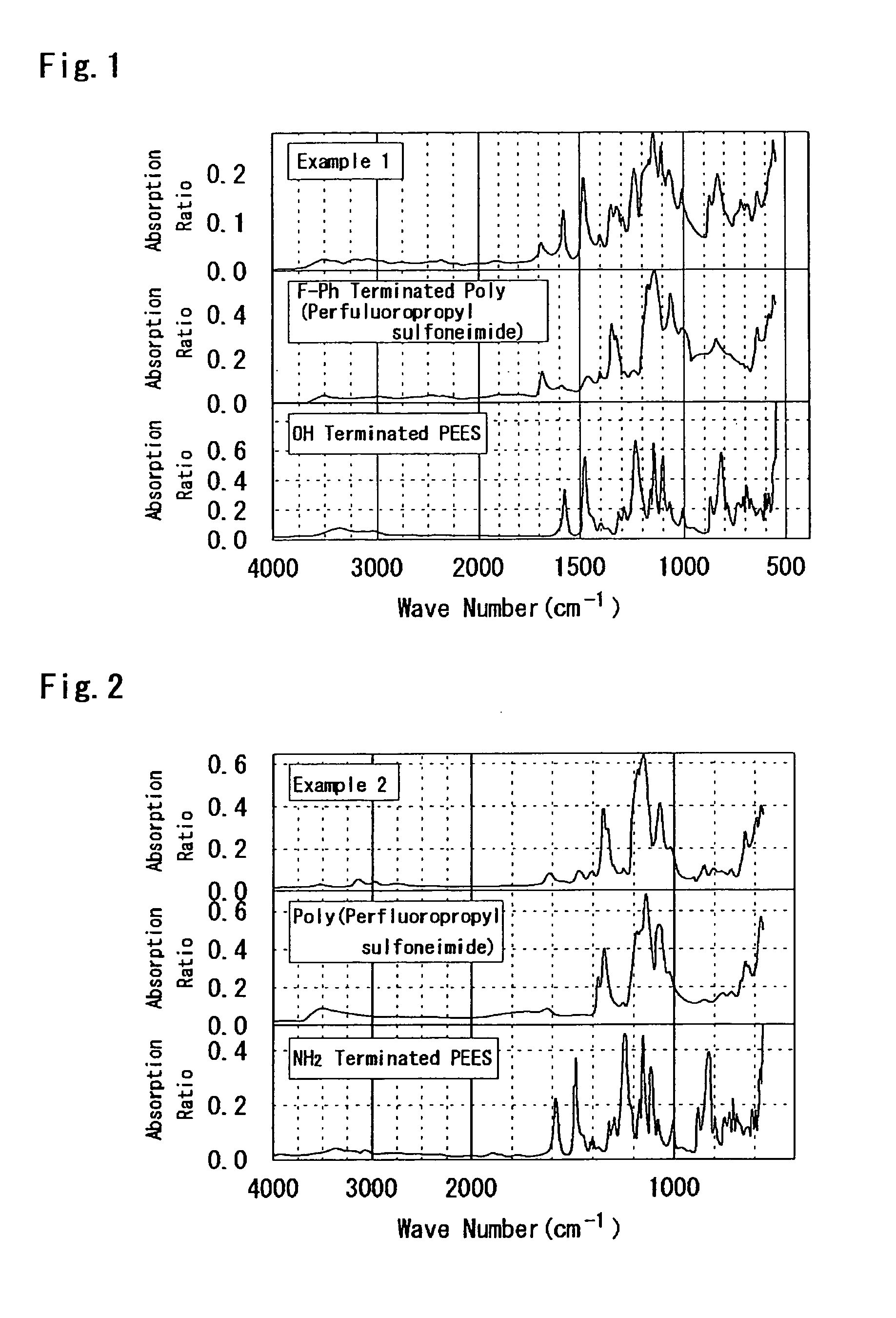
[0250]According to the following process, PEES-block-poly(perfluoropropyl sulfoneimide) was synthesized. That is, to a 50 mL flask, NH2 terminated PEES: 0.96 g (0.1 mmol), C3A: 2.48 g (8 mmol), C3F: 2.53 g (8 mmol), triethylamine: 8.8 mL, and DMAc / DMSO (2 / 1): 15 mL were added, and heated at 90° C. for 10 days. After that, the solvent was removed by distillation, and the reaction product was washed with the NaOH aqueous solution, heated in the 3N H2SO4 aqueous solution at 50° C. for 12 hours, and heated in water at the same temperature for 12 hours. In addition, this was reprecipitated in THF to obtain a desired product (150 mg). The following Formula (c.2) illustrates the synthesis scheme thereof.

[0251]

1.3.3 Electrolyte 3


PUM

PropertyMeasurementUnit
boiling pointaaaaaaaaaa
temperatureaaaaaaaaaa
conductivityaaaaaaaaaa

Abstract

An electrolyte having a structure where a fluorinated hydrophilic segment A represented by -E2-[Rf-E1]m- and a hydrocarbon hydrophobic segment B are alternately bonded to each other through chemical bond and a production process therefor, and an electrolyte membrane, a production process therefor, a catalyst layer and a fuel cell using the same. Rf is a linear or a branched perfluoro chain having one or more carbon atoms, E1, and E2 are each a proton conductive portion represented by Formula —(CONM)i1(CO)i2(SO2NM)i3(SO2)i4— (0≦i1, 0≦i2≦1, 0≦i3, 0≦i4≦1, 0<i1+i3, i1 to i4 are each an integer, and M is proton, alkali metal, or alkali earth metal), 2≦m (m is an integer), and Rf, E1, and E2 may be each arbitrarily selected in the repeating unit.

Description

BACKGROUND OF THE INVENTION[0001]1. Field of the Invention[0002]The present invention relates to an electrolyte, a production process therefor, an electrolyte membrane, a production process therefor, a catalyst layer and a fuel cell, and more particularly, to an electrolyte that is capable of being used in an electrolyte membrane and an electrolyte in a catalyst layer that are used in various electrochemical devices such as fuel cells, a production process therefor, and an electrolyte membrane, a production process therefor, a catalyst layer and a fuel cell using the electrolyte.[0003]2. Description of the Related Art[0004]A solid polymer fuel cell uses a membrane electrode assembly (MEA) in which electrodes are attached to both sides of a solid polymer electrolyte membrane as a basic unit. In addition, in the solid polymer fuel cell, an electrode generally has a two layer structure of a diffusion layer and a catalyst layer. The diffusion layer is a layer to provide a reaction gas a...

Claims


Application Information

Patent Timeline
Patent Type & Authority Patents(United States)
IPC IPC(8): H01M8/10
CPCC08G65/007C08J5/2243C08J5/225H01B1/122H01M8/1027H01M8/103H01M8/1032H01M8/1039H01M8/1072C08J2381/06H01M2008/1095H01M2300/0082Y02E60/521Y02P70/50Y02E60/50
Inventor HOSHIKAWA, NAOHIROHASEGAWA, NAOKIHOSOKAWA, YOICHIKAWASUMI, MASAYASHINOHARA, AKIHIROTANAKA, HIROMITSUTAKAMI, MASAYOSHIYOSHIDA, TOSHIHIKO
Owner TOYOTA CENT RES & DEV LAB INC
Why Eureka
Try Eureka