Closed-loop wavefront sensor using field programmable gate array

a gate array and wavefront sensor technology, applied in the field of sensor systems, can solve the problems of limited use of optical signals in these applications, the effect of the atmosphere on optical signals, and the effect of twinkling or blurring

Inactive Publication Date: 2006-11-16
THE BOEING CO
View PDF25 Cites 8 Cited by
  • Summary
  • Abstract
  • Description
  • Claims
  • Application Information

AI Technical Summary

Benefits of technology

[0006] A field programmable gate array (FPGA) system may be programmed such that the FPGA system will determine wavefront data representative of a wavefront aberration. For example, the FPGA system may execute a phase diversity algorithm that converges on the accurate wavefront data through successive algorithm cycles achieved as part of a feedback configuration in the FPGA system.

Problems solved by technology

Despite showing promise, there are limitations to using optical signals in these applications.
One limitation is the effect the atmosphere has on optical signals.
This air turbulence can produce a twinkling or blurring effect that degrades the laser beam.
The beam distortion and expansion that results from this turbulence alters the wavefront on the laser beam and prevents proper beam focusing, which in turn can mean that the detected image may be indiscernible or unusable.
These techniques, however, are only as accurate as the wavefront sensors they employ.
Hartmann wavefront sensors, which measure wavefront distortion using point sources as a reference beam against an obtained image, are problematic because they require the generation of a separate reference beam, if a star or point source is not immediately available.
This requirement adds to device complexity and can introduce additional sources of scattered light.
Yet, current phase diversity algorithms require time-consuming microprocessor processing.
These microprocessor systems are programming intensive at the front end and, due to the sequential nature of code execution and other factors, too slow at the back end when the algorithm is executed.
No matter the processing speed of the microprocessor core, such systems may take seconds or minutes to complete a full phase diversity correction cycle of an object image.
This is too slow for many applications, including real time imaging.

Method used


Image

  • Closed-loop wavefront sensor using field programmable gate array
  • Closed-loop wavefront sensor using field programmable gate array
  • Closed-loop wavefront sensor using field programmable gate array

Examples


example phase diversity

Formulation

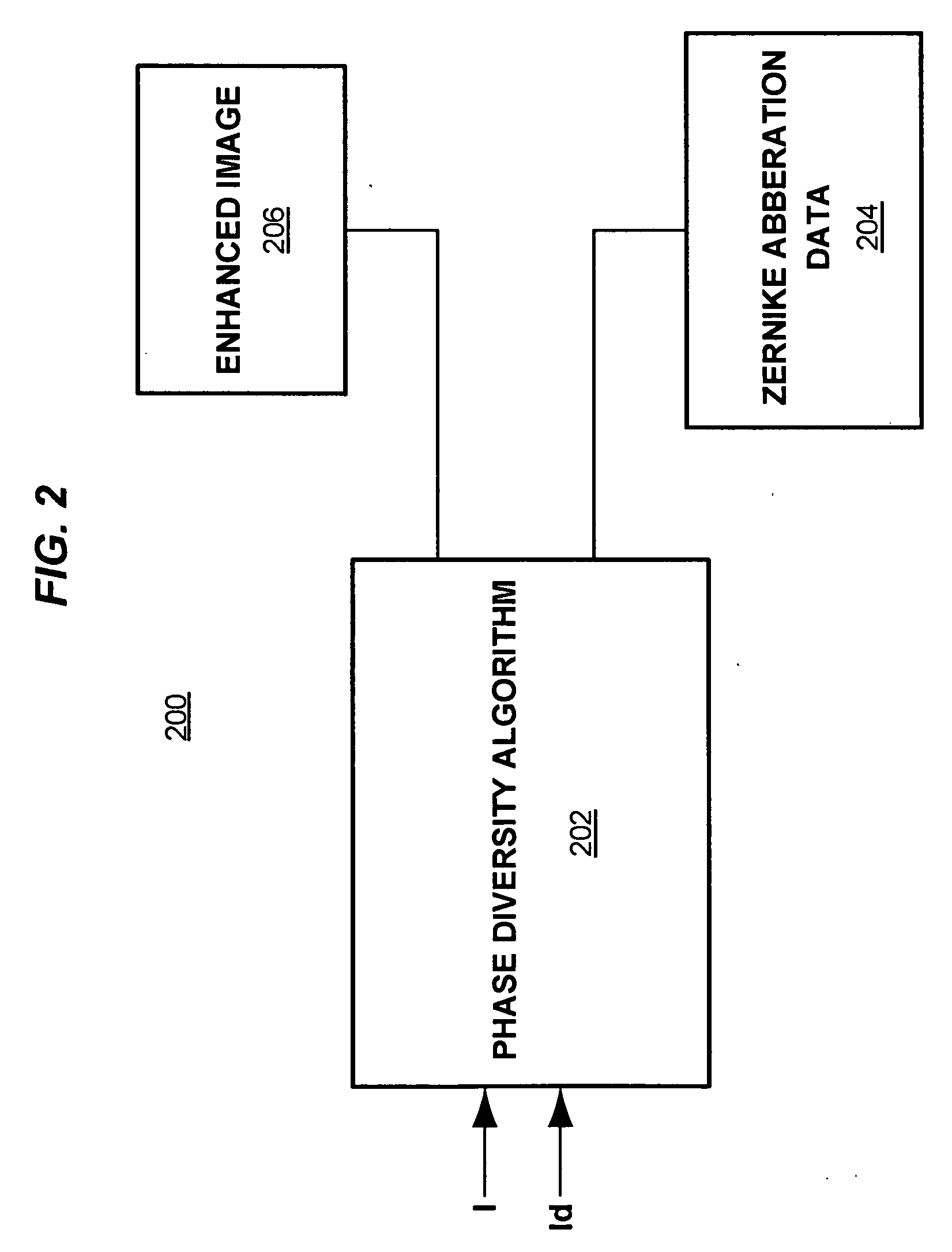
[0032] By way of example, not limitation an example phase diversity computation technique will not be described. The diversity image equation id(x,y) at the image plane of an isoplanatic imaging system is given by:

id(x,y)=fdo{circle around (×)}hd(x,y)+nd(x,y)   (1)

where o(x,y) is the pristine object absent wavefront aberrations, hd(x,y), the intensity point spread function (psf), {circle around (×)}, the convolution operator, nd(x,y), the independent and identically distributed (iid) noise process, and fd, the fraction of the average of total photocounts going to diversity sensor d with ∑d⁢fd=1,

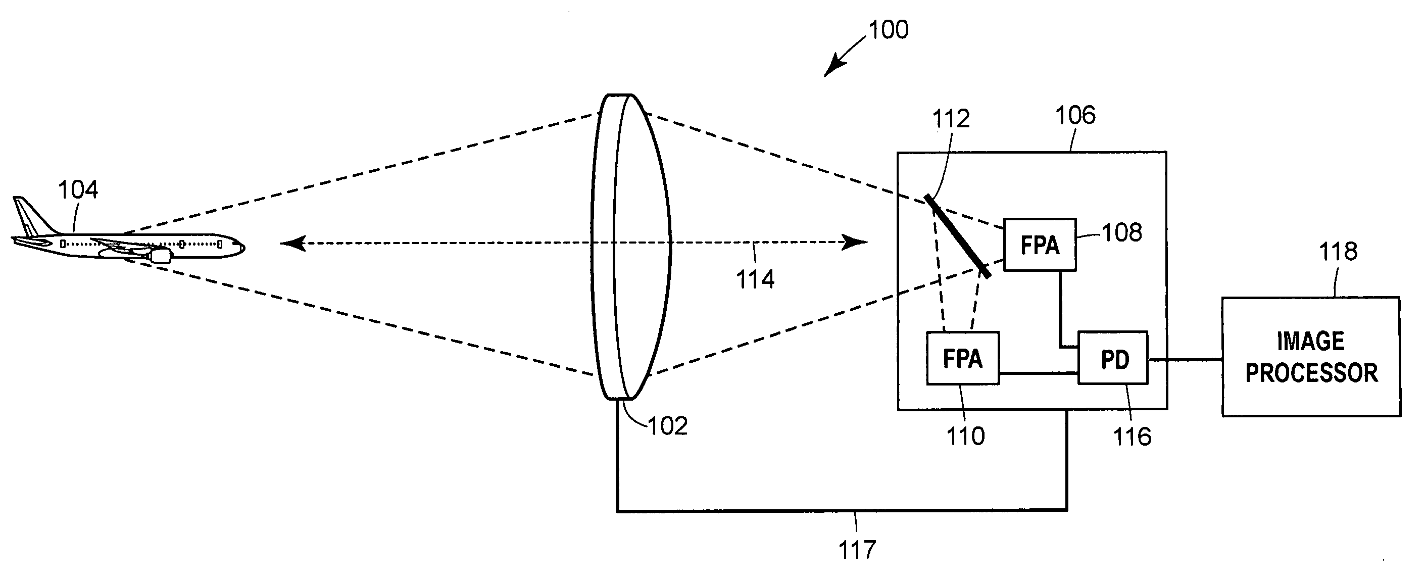
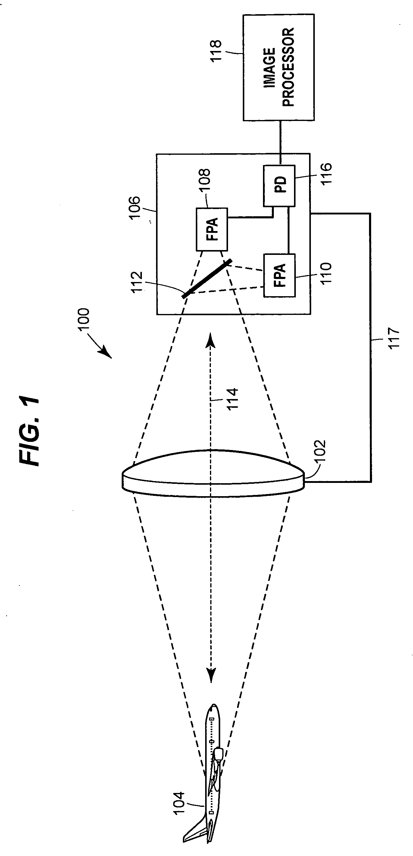
assuming no losses. In the case of two diversity images, the first diversity image i1(x, y) (in the example of FIG. 1, the “in-focus” image) and the first psf h1(x, y) are denoted by i(x, y) and h(x, y), respectively. The second diversity image i2(x, y) (in the example of FIG. 1, the “out-of-focus” image) and the second psf h2(x, y) are denoted by id(x, y) and hd(x, y), and ar...


PUM


Abstract

A system capable of determining wavefront characteristics, such as air induced wavefront aberrations, includes a field programmable gate array (FPGA) device executing a phase diversity algorithm. The FPGA device can be a stand-alone device or comprise multiple FPGAs. The device receives an “in-focus” and an “out-of-focus” image having a known optical difference from that of the “in-focus” image. The device then performs as many phase diversity algorithm iterations as desired to reach an expression for the wavefront aberrations induced on the collected image data. The resulting wavefront data may be used to produce an enhanced image of the original image data. Example applications include remote sensors and targeting systems, and both passive imaging and active projection systems that compensate for wavefront anomalies.

Description

FIELD OF THE DISCLOSURE [0001] The present disclosure relates generally to sensor systems and, more particularly, to optical sensors to correct for wavefront anomalies, such as, atmospheric turbulence or thermal blooming, in a distorting medium. BACKGROUND OF RELATED ART [0002] Numerous remote target applications, such as high-bandwidth communications and long distance imaging systems, now use over-the-air optical signals for information transfer. Tactical high-energy laser (HEL) systems, for example, communicate optical signals over large distances for object identification and aimpoint controls in laser guided weapons systems. These systems allow operators to identify objects from distances large enough to protect operator safety, but close enough to allow somewhat accurate identification. [0003] Despite showing promise, there are limitations to using optical signals in these applications. One limitation is the effect the atmosphere has on optical signals. In a targeting system, f...

Claims


Application Information

Patent Timeline
Patent Type & Authority Applications(United States)
IPC IPC(8): G01J1/00
CPCG01J9/00G02B26/06G02B27/0025
Inventor DOLNE, JEAN J.SCHALL, HAROLD B.MENICUCCI, PAUL J.
Owner THE BOEING CO
Why Eureka
Try Eureka