Mounting mat for a catalytic converter

a technology of catalytic converter and mounting mat, which is applied in the field of mounting mat, can solve the problems of increasing the gap between the inside peripheral wall of the housing and the outer wall of the monolith, the fragility of the monolith used in the pollution control device, and the inability to withstand vibration or shock damage, etc., and achieves the effect of sufficient holding force and low cos

Inactive Publication Date: 2006-11-16
3M INNOVATIVE PROPERTIES CO
View PDF21 Cites 37 Cited by
  • Summary
  • Abstract
  • Description
  • Claims
  • Application Information

AI Technical Summary

Benefits of technology

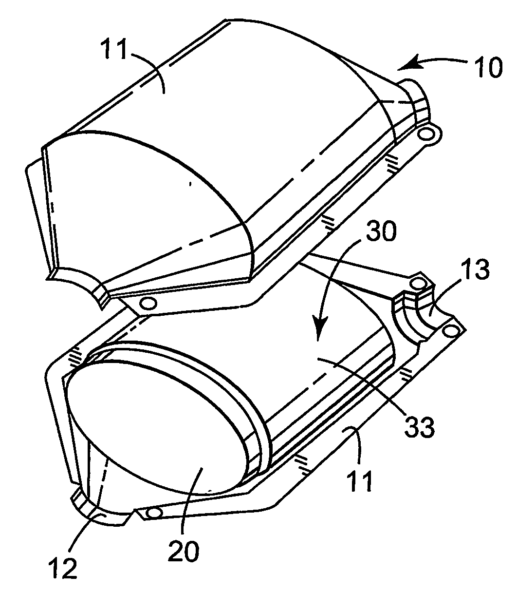
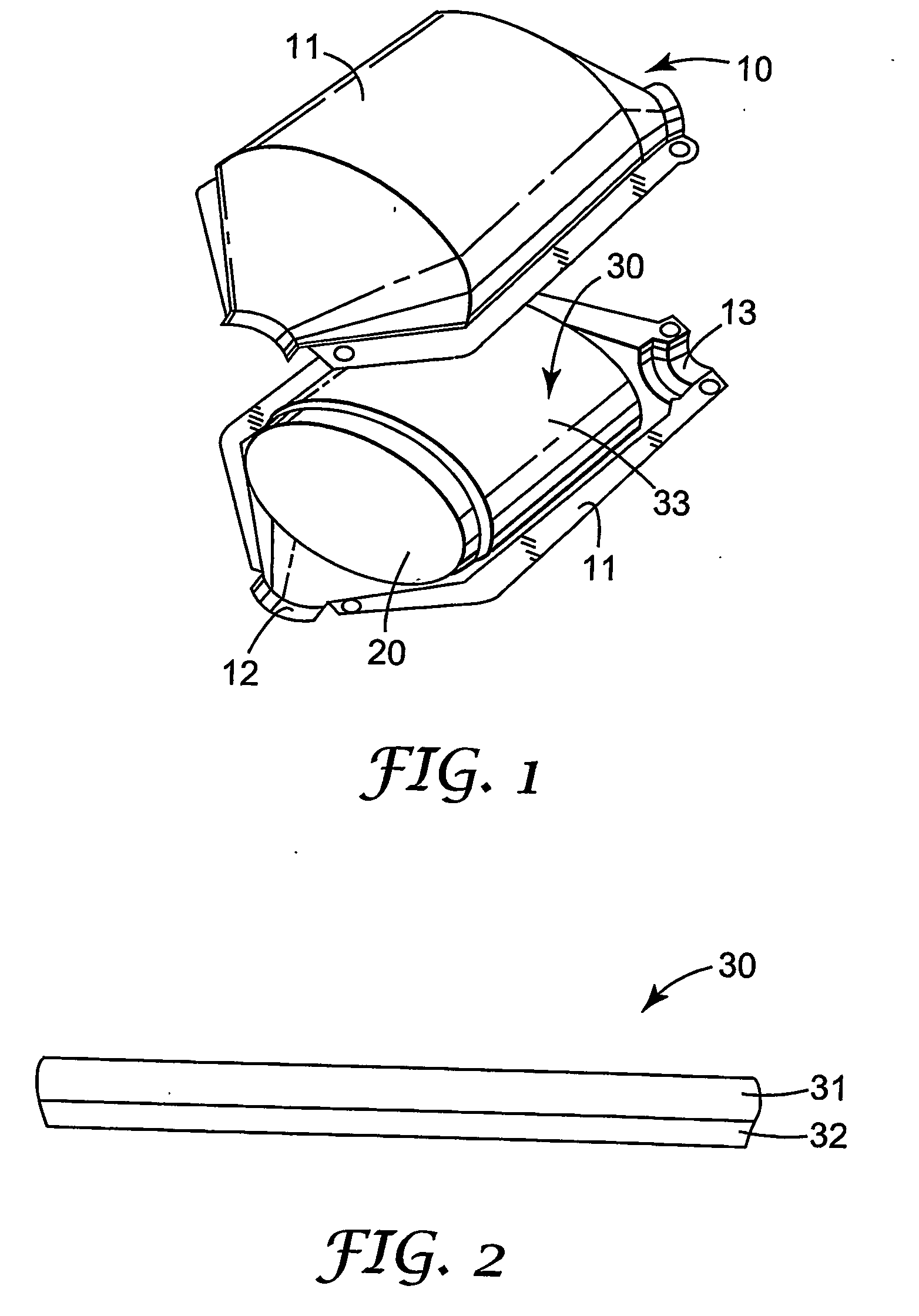
[0018] It was found that the mounting mat according to the invention can be produced at a much lower cost than mounting mats based on a single layer of polycrystalline fibers. Also, when mounting the pollution control monolith in the pollution control device in such a way that the layer of the ceramic fibers obtainable from a sol-gel process faces the monolith, a sufficient holding force can be maintained both at low and high temperatures and during the cycling between low and high temperature during the life time of the pollution control device that occurs when the pollution control device is used in for example a motor vehicle.

Problems solved by technology

The monoliths and in particular the ceramic pollution control monoliths, used in pollution control devices are fragile and susceptible to vibration or shock damage and breakage.
This means that as the pollution control device is heated the gap between the inside peripheral wall of the housing and the outer wall of the monolith increases.
Such thermal cycling occurs hundreds of times during the life and use of the pollution control device.
Because of the reduced wall thickness, these monoliths are even more susceptible to damage and accordingly, the mounting mats for mounting such monoliths are subject to more stringent requirements.
Intumescent mounting mats have the disadvantage that they may exert too much pressure on the pollution control monolith during use when the pollution control monolith heats up.
As a result, intumescent mounting mats are less suitable for mounting thin wall and ultra-thin wall monoliths.
Such mounting mat may however not have sufficient holding strength to satisfactorily mount thin wall and ultra-thin wall monoliths at high temperature and protect them against shock and damage.
The mat is apparently meant for thermal insulation and would not be readily suitable as a mounting mat for mounting a pollution control monolith in a pollution control device.
Also, there is no teaching as to how such a bilayer mat is to be used as a mounting mat.
Unfortunately, polycrystalline fibers are much more expensive than melt formed ceramic fibers such as ceramic glass fibers and as a result mounting mats of polycrystalline fibers are often prohibitively expensive.

Method used


Image

  • Mounting mat for a catalytic converter
  • Mounting mat for a catalytic converter

Examples


example 1

[0053] The mounting mat of Example 1 consisted of a layer of mat of A1 having a bulk density of 0.16 g / cc placed on top of a layer of mat B having a bulk density of 0.12 g / cc. The combined mat had a bulk density of approximately 0.14 g / cc. See Table 1 below.

[0054] The real condition fixture test (RCFT) was conducted by the method described above under Test Method. The two layer mat of Example 1 was tested by placing the polycrystalline fiber layer side of the mat towards the hotter side of the RCFT test assembly and the R glass fiber layer side of the mat towards the cooler side of the RCFT test assembly and compressing the dual layer mat to a mount density of 0.35 g / cc prior to the start of the test. This resulted in a starting pressure at room temperature of 217 kPa.

[0055] RCFT results are summarized in Table 2. During the first temperature cycle, the mat showed a pressure of 55 kPa at the peak temperature. During the third temperature cycle, the mat showed a pressure of 43 kPa ...


PUM

PropertyMeasurementUnit
densityaaaaaaaaaa
lengthaaaaaaaaaa
number average diameteraaaaaaaaaa

Abstract

The present invention provides a mounting mat (30) for mounting a pollution control monolith (20) in a pollution control device (10). The mounting mat has a bulk density of 0.12 to 0.3 g/cm3 and comprises (i) a layer of chopped magnesium aluminium silicate glass fibers and (ii) a layer of ceramic fibers obtainable from a sol-gel process. Preferably, the layer of chopped magnesium aluminium silicate glass fibers and the layer of ceramic fibers define opposite major surfaces of the mat. The present invention further provides a pollution control device (10), comprising a pollution control monolith (20) arranged in a metallic casing (11) with the mounting mat (30) disposed between the metallic casing (11) and pollution control monolith (20).

Description

FIELD OF THE INVENTION [0001] The present invention relates to a mounting mat for mounting a pollution control monolith in a pollution control device. In particular the present invention relates to a mounting mat that is comprised of a layer of glass fibers and a layer of ceramic fibers obtainable from a sol-gel process. The invention further relates to a pollution control device. BACKGROUND OF THE INVENTION [0002] Pollution control devices are universally employed on motor vehicles to control atmospheric pollution. Two types of devices are currently in widespread use—catalytic converters and diesel particulate filters or traps. Catalytic converters contain a catalyst, which is typically coated on a monolithic structure mounted within a metallic housing. The monolithic structures are typically ceramic, although metal monoliths have also been used. The catalyst oxidizes carbon monoxide and hydrocarbons and reduces the oxides of nitrogen in automobile exhaust gases to control atmosphe...

Claims


Application Information

Patent Timeline
Patent Type & Authority Applications(United States)
IPC IPC(8): B01D53/34
CPCB01D46/10F01N3/2864B01D2279/30B32B5/022B32B5/06B32B5/26B32B17/02B32B2250/02B32B2250/20B32B2262/101B32B2262/105B32B2264/102B32B2307/308B32B2307/704B32B2307/72F01N3/2853B01D46/2422
Inventor MERRY, RICHARD P.
Owner 3M INNOVATIVE PROPERTIES CO
Why Eureka
Try Eureka