Machine assisted laminator and method

a technology of laminator and machine, applied in the direction of mechanical control device, process and machine control, instruments, etc., can solve the problems of reducing lay-down rate, reducing the use rate of narrower course material, and prone to wrinkles in course material

Active Publication Date: 2006-11-23
THE BOEING CO
View PDF13 Cites 75 Cited by
  • Summary
  • Abstract
  • Description
  • Claims
  • Application Information

AI Technical Summary

Benefits of technology

[0006] The foregoing needs are met, to a great extent, by the present invention, wherein in one respe

Problems solved by technology

In addition, the wider the course is, the more prone the course material is to wrinkle.
However, for contoured items, the natural path of adj

Method used


Image

  • Machine assisted laminator and method
  • Machine assisted laminator and method
  • Machine assisted laminator and method

Examples


Embodiment Construction

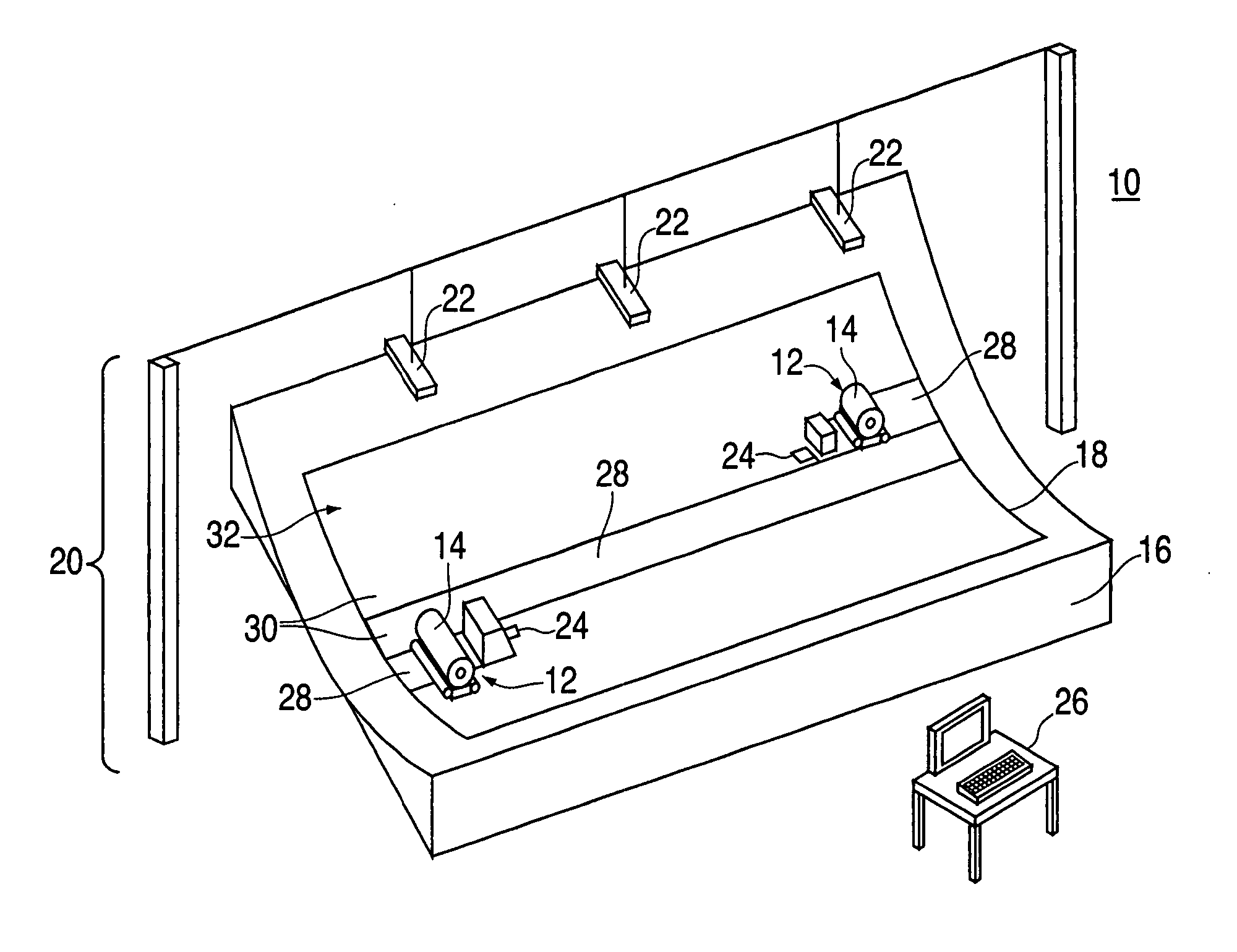
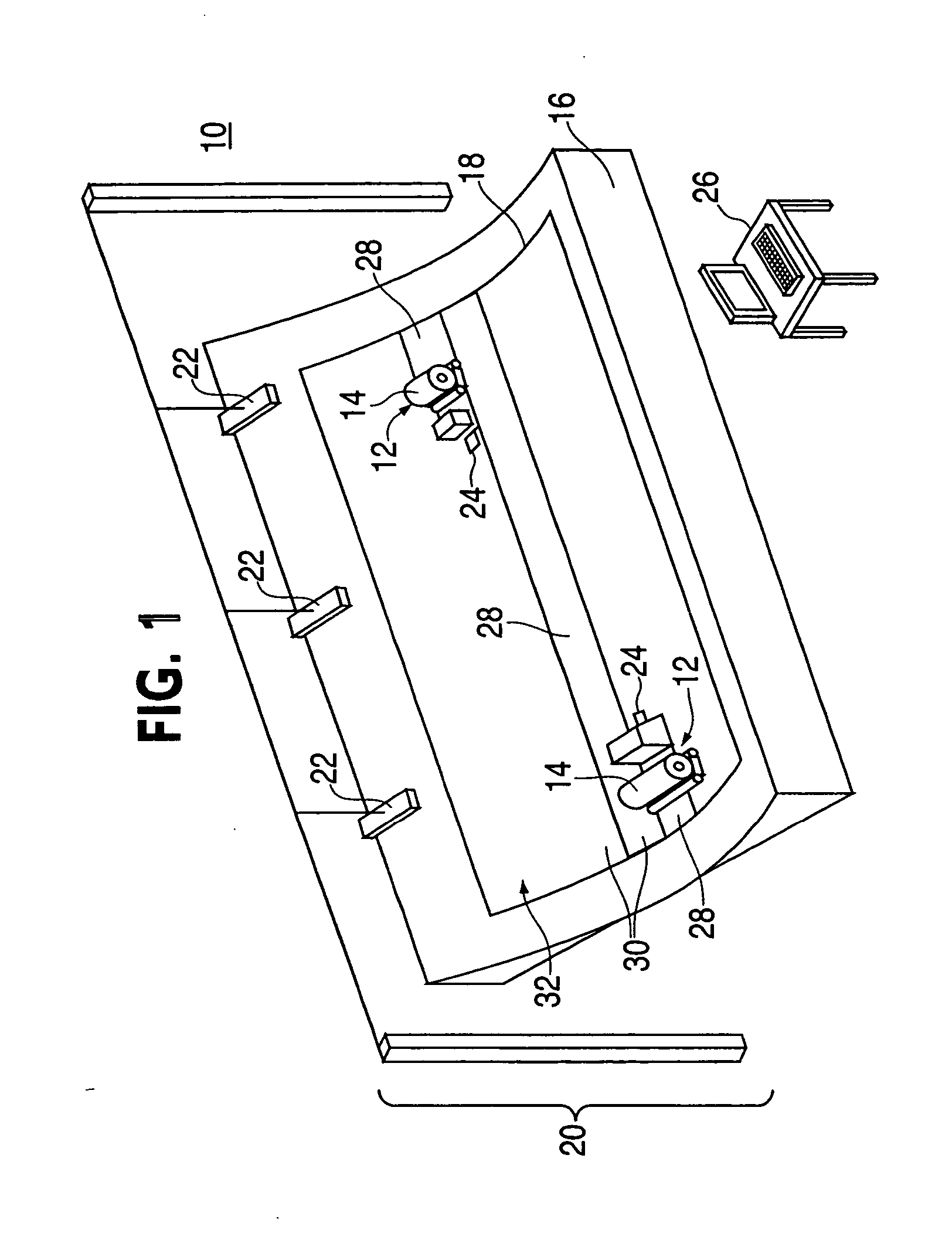
[0020] The invention will now be described with reference to the drawing figures, in which like reference numerals refer to like parts throughout. As shown in FIG. 1, a machine assisted laminator 10 (“MAL”) suitable for use in an embodiment of the invention includes one or more robotic vehicles 12 to position a ply material 14 upon a form 16 to generate an item 18. The robotic vehicles 12 are guided by a guidance system 20. The guidance system 20 includes one or more laser emitters 22, laser receivers 24, and a control unit 26. The control unit 26 is configured to receive instructions from a user and forward instructions to the laser emitters 22. The laser emitters 22 are configured to forward signals, via laser, to the laser receivers 24 and thereby control the movement of the robotic vehicles 12. In this manner, a set of computer readable instructions are utilized by the MAL 10 to fabricate the item 18. A more detailed description of the robotic vehicles 12 and the guidance system...


PUM

PropertyMeasurementUnit
Temperatureaaaaaaaaaa
Pressureaaaaaaaaaa

Abstract

A system to fabricate a composite item includes an end effector, robotic vehicle, sensor, and cutting system. The end effector applies a course to a layup form. The robotic vehicle positions the end effector. The sensor senses an edge of a previously applied course. The cutting system cuts a profile on the course in response to the sensed edge.

Description

FIELD OF THE INVENTION [0001] The present invention generally relates to a ply placement device. More particularly, the present invention pertains to a device for and method of placing plies on a surface. BACKGROUND OF THE INVENTION [0002] Composite items are generally constructed from layers of material that are laminated together. These layers are often referred to as partial or full plies. For structures exceeding the available material width, each layer is typically made up of a series of strips or courses of material placed edge to edge next to each other or are overlapped to some extent. Each ply may be in the form of woven fibers in a fabric, unidirectional fiber material, metal foils, adhesive films or a variety of other conformations. Unidirectional fiber material is often termed, “tape.” The fibers may be made from any of a multitude of natural and / or “man-made” materials such as fiberglass, graphite, Kevlar®, and the like. [0003] The courses are generally laid upon the fo...

Claims


Application Information

Patent Timeline
IPC IPC(8): B32B37/00
CPCB29C70/388Y10T156/108B29C2793/0027B29C70/545B29C70/38G05D1/00
Inventor LAUDER, ARNOLD J.MCDONALD, TREVOR M.LEDET, ROGER J.BOONSTRA, DAVIDFERREIRA, ANTONIOBARRETT, KEVIN C.YESTRAU, JOHN
Owner THE BOEING CO
Why Eureka
Try Eureka