Sound absorber and sound absorbing device

a technology of sound absorber and sound absorber, which is applied in the direction of sound producing device, instruments, flooring, etc., can solve the problems of insufficient sound absorber sound absorber, insufficient see-through capability, and insufficient reflection light to see the inside through, so as to achieve good sound absorber ability and reduce nois

Inactive Publication Date: 2006-11-23
NAGATA KOSAKUSHO CO LTD
View PDF30 Cites 18 Cited by
  • Summary
  • Abstract
  • Description
  • Claims
  • Application Information

AI Technical Summary

Benefits of technology

[0010] It is, therefore, an object of the present invention to provide a sound absorber which can attenuate sound waves in a wide frequency band effectively using interference caused by an air layer and diffuse reflection caused by a sound wave reflector in addition to the sound absorbing ability of a material such as a sound absorbent, and to provide a sound absorbing device having a good sound absorbing ability and having a see-through capability and a ventilating capability.

Problems solved by technology

However, the sound absorbing ability of the circular cylindrical sound absorber disclosed in the Patent Document 1 is still unsatisfactory.
The sound absorbing device in which the circular cylindrical sound absorbers and a transparent plate are combined has a problem in the see-through capability.
On top of that, it has been proven that when the sound absorbing device is illuminated from outside with a light source such as a flashlight, most of the illuminating light is reflected on the transparent plate and the reflected light is too bright to see the inside through it.
Thus, when the noise absorbing device is installed around a large machine which generates large noise, it causes great inconvenience since visual inspection cannot be carried out from outside.
Additionally, since the transparent plate has a see-through capability but has no ventilating capability, that is, does not allow air to pass through it, its application in places where ventilation is required is limited.
For example, when the sound absorbing device is installed around an office or residence, it causes discomfort since sufficient ventilation cannot be obtained.
When the sound absorbing device is installed outdoors such as along a highway, it may adversely affect the natural environment since it blocks the flow of wind, for example.

Method used


Image

  • Sound absorber and sound absorbing device
  • Sound absorber and sound absorbing device
  • Sound absorber and sound absorbing device

Examples


first embodiment

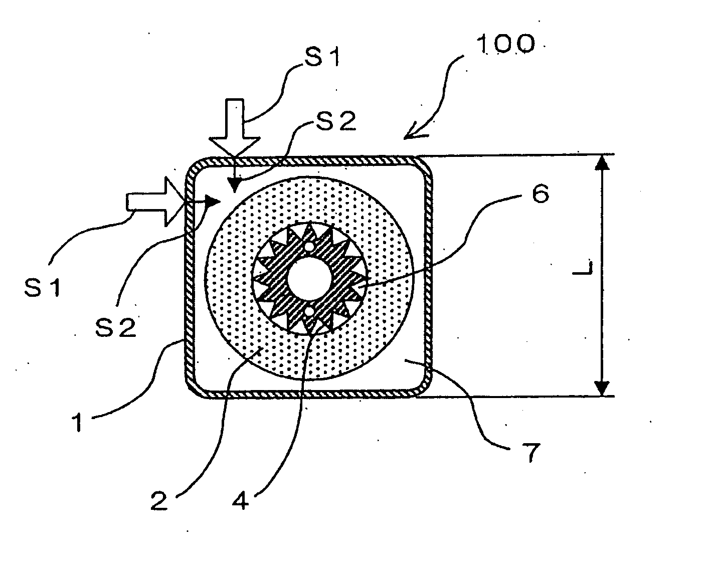
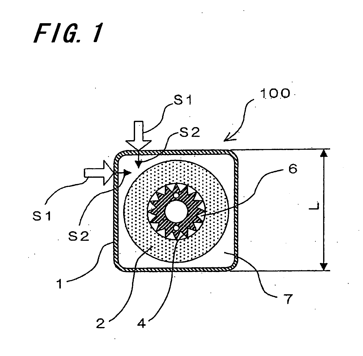
[0072]FIG. 8 is a cross-sectional view illustrating a sound absorber 101 of a first embodiment according to the fifth technical means. The sound absorber 101 has a first air layer 71 defined by a tubular porous sheath 11 having a generally rectangular cross-section with sides having sawtooth-shaped projections and depressions.

second embodiment

[0073]FIG. 9 is a cross-sectional view illustrating a sound absorber 102 of a second embodiment according to the seventh technical means. The sound absorber 101 has a first air layer 72 defined by a tubular porous sheath 12 having a generally triangular cross-section. As shown in FIG. 9, sound waves S1 emitted from unidentified directions and having reached the surfaces of the porous sheath 12 enter the first air layer 72 as sound waves S2 directed generally perpendicular to the surfaces of the porous sheath 12 and are transmitted into the air layer 72.

third embodiment

[0074]FIG. 10 is a cross-sectional view illustrating a sound absorber 103 according to the eighth technical means. The sound absorber 103 has a first air layer 73 defined by a tubular porous sheath 13 having a generally isosceles trapezoidal cross-section. The height H of the isosceles trapezoid may be generally the same as the length L of one side of the generally rectangular cross-section of the first technical means shown in FIG. 1. As shown in FIG. 10, sound waves S1 emitted from unidentified directions and having reached the surfaces of the porous sheath 13 enter the first air layer 73 as sound waves S2 directed generally perpendicular to the surfaces of the porous sheath 13 and are transmitted into the air layer 73.


PUM


Abstract

A sound absorber according to the present invention comprises: a tubular porous sheath with a non-circular cylindrical cross-section; a circular cylindrical soft fiber sound absorbent disposed inside the porous sheath in partial contact or non-contact with the porous sheath with the longitudinal direction thereof aligned with the longitudinal direction of the porous sheath; and a bar-like core with a non-circular cylindrical cross-section disposed inside the soft fiber sound absorbent in a partial contact or non-contact with the soft fiber sound absorbent with the longitudinal direction thereof aligned with the longitudinal direction of the soft fiber sound absorbent. A sound absorbing device according to the present invention comprises a plurality of the sound absorbers arranged side by side at specific intervals in two or more rows in a staggered configuration. Alternately, a plurality of sound absorbers having a generally isosceles trapezoidal cross-section are arranged in a row with the upper and lower bases of the isosceles trapezoidal cross-sectional shape thereof exposed to the outside alternately.

Description

CROSS REFERENCE OF RELATED APPLICATIONS [0001] The disclosure of Japanese Patent Application No. 2005-084833 (filed on Mar. 23, 2005) including the specification, claims, drawings and abstract is incorporated herein by reference in its entirety. BACKGROUND OF THE INVENTION [0002] 1. Field of Invention [0003] The present invention relates to a sound absorber for use in a sound insulating wall for absorbing noise, and a sound absorbing device using the sound absorber. [0004] 2. Background Art [0005] Various types of sound absorbers and sound absorbing devices are used to absorb noise generated by large machines or vehicles running on highways and railroad tracks. Conventionally, board-like sound absorbing panels composed of a thin film bag filled with a soft fiber sound absorbent and porous plates are widely used in sound absorbing devices. Recently, a circular cylindrical sound absorber having an improved sound absorbing ability and a sound absorbing device using the sound absorbers ...

Claims


Application Information

Patent Timeline
Patent Type & Authority Applications(United States)
IPC IPC(8): E04B1/82
CPCE01F8/0082G10K11/16E04B9/34E04B1/8209
Inventor NAKAGAWA, TETSUTAROHNAGATA, SHINYA
Owner NAGATA KOSAKUSHO CO LTD
Why Eureka
Try Eureka