Tundish stopper rod for continuous molten metal casting

a stopper rod and continuous molten metal technology, applied in the field of stopper rods, can solve the problems of inclusions, typically present, and detrimentally affecting the flow control characteristics of the stopper rod

Inactive Publication Date: 2006-11-23
REFRACTORY INTELLECTUAL PRORERTY GMBH & CO KG
View PDF7 Cites 4 Cited by
  • Summary
  • Abstract
  • Description
  • Claims
  • Application Information

AI Technical Summary

Benefits of technology

[0003] The continuous casting of molten metal involves providing an available source of molten metal in a suitable vessel, for example, a tundish or ladle, which is located physically above a mould in the continuous casting apparatus. When using a tundish as the vessel for holding the molten metal, a flow of molten metal is discharged therefrom into the mould via a tundish discharge nozzle at a flow rate which is suitable for the casting conditions. The flow rate of molten metal being discharged from the tundish nozzle is controllably regulated by a stopper rod. More specifically, the stopper rod is moveable relative to the tundish nozzle between seated and unseated conditions. Thus, movement of the stopper rod relative to the tundish nozzle will selective adjust the annular orifice area defined between the stopper rod tip and the tundish nozzle through which molten metal is allowed to flow. Adjustably varying the effective annular orifice area will thereby in turn adjustably control over the flow rate of the molten metal being discharged from the tundish.
[0007] The main source of flow control in a tundish using stopper rods is the shape of the stopper tip. Most of the stoppers in the continuous casting industry have rounded tips with different radiuses. When a rounded tip is used steel forms a very thick boundary layer where fluid velocities are very small. Then just at the tip a stagnant zone is formed and any inclusion that touches that area loses momentum and can be easily trapped on the ceramic surface of the tip becoming, with time, into a clogging problem. Moreover, rounded tips enhance boundary layer thickness in zones upstream the tip and these are prone for inclusions trapping increasing danger of nozzle clogging.
[0008] It would therefore be desirable if a stopper rod for continuous molten metal casting could be provided which minimizes (if not eliminates entirely) deposition of inclusions onto the stopper rod tip thereby allowing the stopper rod to be maintained in service for prolonged time periods and / or improving steel cleanliness. It is towards fulfilling such a need that the present invention is directed.
[0009] Broadly the present invention is embodied in a stopper rod for continuous molten metal casting which creates flow profiles of the molten metal as it is being discharged from a vessel holding the molten metal through a nozzle so as to enhance metal cleanliness. That is, the stopper rods according to the present invention discourage the deposition of inclusions (e.g., undesirable particulates, such as metal oxides) onto the stopper rod tip. According to one especially preferred aspect of the present invention, a stopper rod for continuous molten metal casting is provided which has a geometric profile so as to increase the velocity of the flowing molten metal sufficient to reduce the boundary layer thickness of such flowing molten metal adjacent the nozzle and stopper rod tip surfaces so as to minimize the deposition of inclusions thereon.
[0010] Advantageously, the geometric profile of the stopper rod tip according to the present invention also does not detrimentally affect the lifting force sensitivities of the stopper rod. That is, the geometric profile of the stopper rod tip does not create molten metal flow profiles which would make it difficult to exercise physical displacement of the stopper rod tip relative to the tundish nozzle. As a result, the stopper rods of the present invention exhibit a relatively wide range of flow rate control of the molten metal flow discharged from the tundish.
[0015] According to a third aspect of the invention, there is provided a method of regulating the flow rate of molten metal being discharged from a vessel through a discharge nozzle during a continuous casting operation, the method comprising providing a stopper rod comprising a stopper rod body, and a stopper rod tip at a lower end of the stopper rod body, the stopper rod tip having a frustoconically shaped exterior surface which terminates in a recessed nose; and positioning the stopper rod within the vessel so that the stopper rod tip operatively cooperates with the discharge nozzle; and controllably displacing the stopper rod tip relative to the discharge nozzle so as to regulate the flow rate of molten metal being discharged from the vessel through the vessel discharge nozzle.

Problems solved by technology

One problem associated with controlling molten metal flow is that so-called inclusions (e.g., contaminants in the molten metal such as oxidized particles of the metal being cast) are typically present in the molten metal as it is discharged from the tundish through the nozzle.
Over time, therefore, the geometry of the orifice are defined between the tundish nozzle and the stopper rod tip may change due to continual deposit of inclusions thereby eventually detrimentally affecting the stopper rod's flow control characteristics.
A flow condition like this brings about downstream flow instability causing an incomplete useage of a port area in a SEN.
In other words, separation phenomena may bring about instability in the internal walls of a SEN and its ports promoting flow fluctuations, meniscus oscillations of bath in the mould and out of control turbulent spikes of velocity.
All those phenomena induce severe slab defects.
Then just at the tip a stagnant zone is formed and any inclusion that touches that area loses momentum and can be easily trapped on the ceramic surface of the tip becoming, with time, into a clogging problem.
Moreover, rounded tips enhance boundary layer thickness in zones upstream the tip and these are prone for inclusions trapping increasing danger of nozzle clogging.
That is, the geometric profile of the stopper rod tip does not create molten metal flow profiles which would make it difficult to exercise physical displacement of the stopper rod tip relative to the tundish nozzle.

Method used


Image

  • Tundish stopper rod for continuous molten metal casting
  • Tundish stopper rod for continuous molten metal casting
  • Tundish stopper rod for continuous molten metal casting

Examples


examples

[0041] Computer simulations were conducted based on a mathematical fluid turbulence model coupled with a Lagrange model for trajectory of particles. The selected model for momentum transfer was the turbulent regime known as κ-ε. A constant casting rate of 4.0 tons / minute was simulated for each of the stopper rods being examined.

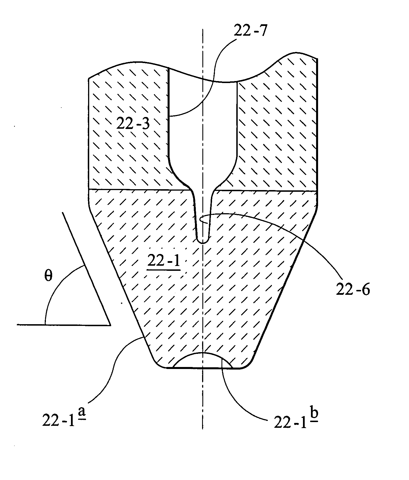
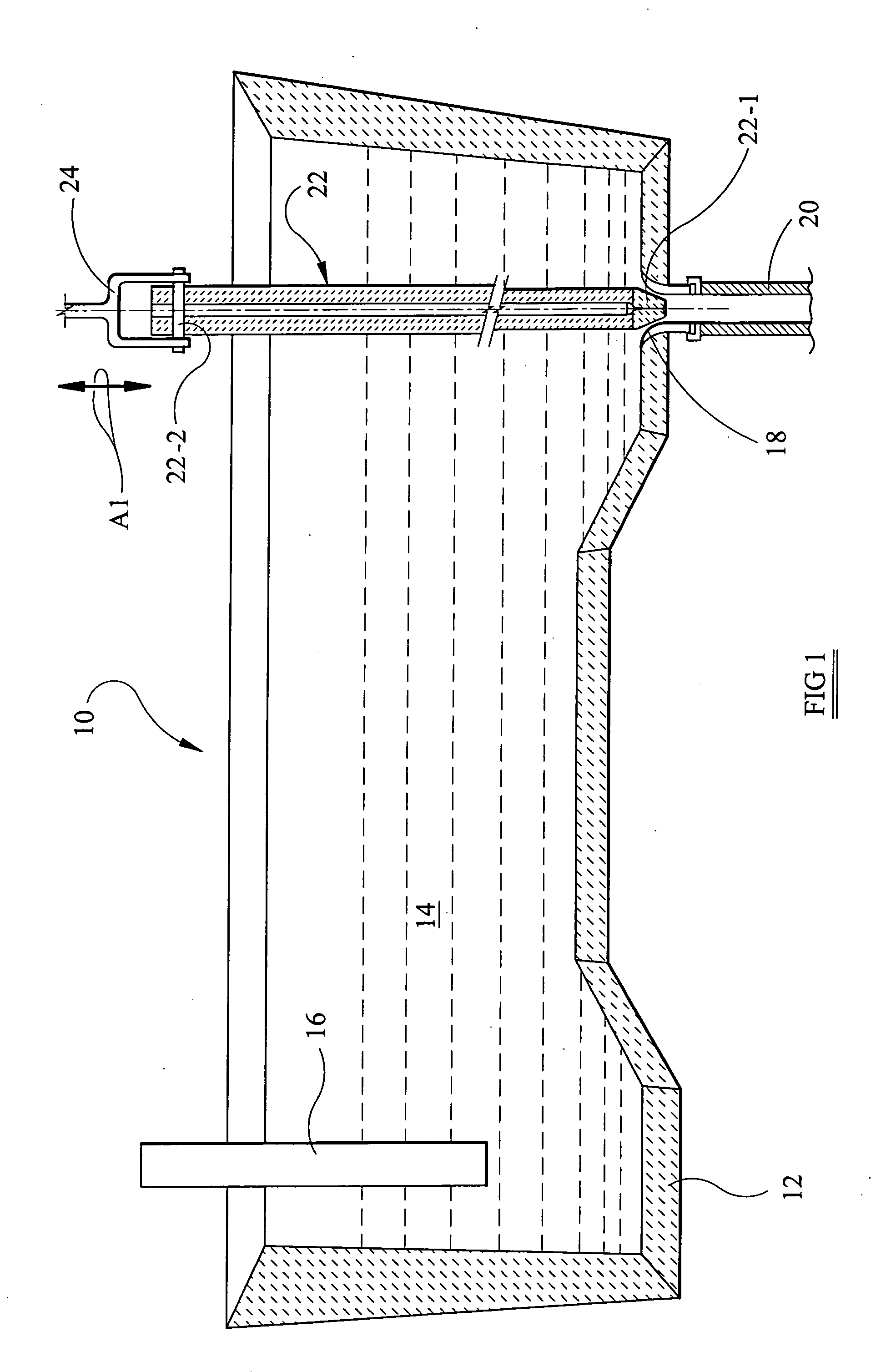
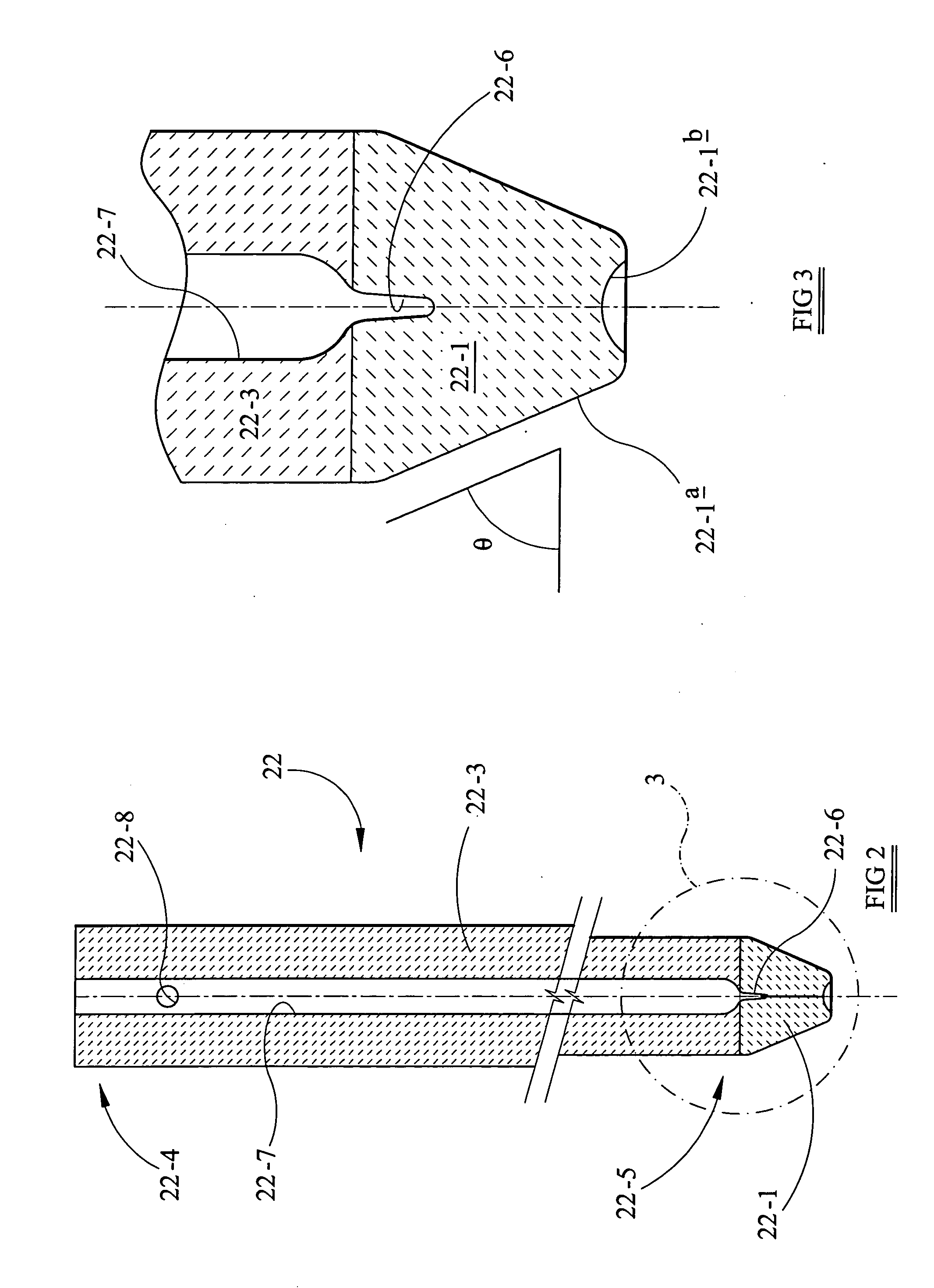
[0042] Comparative Stopper Rod No. 1 (CSR1) was formed with a stopper rod tip configured to have an upper cylindrical surface portion, an intermediate frustoconical surface portion, and a terminal smoothly convex nose. The Comparative Stopper Rod No. 2 (CSR2) was formed with a stopper rod tip having a hemi-ellipsoidal surface configuration. The stopper rod according to the present invention was configured as shown in FIGS. 1-3 above. A bar graph plot of percentage of trapped inclusions to form a clog for each of the stopper rods is shown in FIG. 4. It is evident that the stopper rod according to the present invention results in substantially less percentage ...


PUM

PropertyMeasurementUnit
angleaaaaaaaaaa
angleaaaaaaaaaa
angleaaaaaaaaaa

Abstract

Stopper rods (22) for the continuous casting of molten metal have a stopper rod body (22-3), and a stopper rod tip (22-1) at a lower end of the stopper rod body. The stopper rod tip defines a frustoconically shaped exterior surface (22-1a) which terminates in a recessed nose (22-1b). The recessed nose is most preferably a curvilinear surface (e.g., a spherical segment), but non-curvilinear surfaces (e.g., prismatic, pyramidal, triangular, and quadrangular surfaces) may alternatively be employed. The frustoconically shaped exterior surface (22-1a) of the stopper rod tip most preferably forms an angle θ with respect to a horizontal plane which is sufficiently great so as to increase the velocity of the flowing molten metal to reduce the boundary layer thickness thereof adjacent the nozzle and stopper rod tip surfaces so as to minimize the deposition of inclusions thereon. Preferably the angle θ is greater than 70°.

Description

[0001] This application is a continuation-in-part (CIP) of copending U.S. application Ser. No. 11 / 120,181 filed May 3, 2005, the entire content of which is expressly incorporated hereinto by reference.FIELD OF THE INVENTION [0002] The present invention relates generally to the casting of molten metal, such as steel, copper, aluminium and alloys thereof. More specifically, the present invention relates to stopper rods for regulating the flow rate of molten metal discharged from a tundish during a continuous casting operation. BACKGROUND AND SUMMARY OF THE INVENTION [0003] The continuous casting of molten metal involves providing an available source of molten metal in a suitable vessel, for example, a tundish or ladle, which is located physically above a mould in the continuous casting apparatus. When using a tundish as the vessel for holding the molten metal, a flow of molten metal is discharged therefrom into the mould via a tundish discharge nozzle at a flow rate which is suitable ...

Claims


Application Information

Patent Timeline
Patent Type & Authority Applications(United States)
IPC IPC(8): B22D41/00
CPCB22D41/186B22D41/18B22D41/16
Inventor MORALES, RODOLFO D.GARCIA, LINO D.
Owner REFRACTORY INTELLECTUAL PRORERTY GMBH & CO KG
Why Eureka
Try Eureka