
Battery charging device

Inactive Publication Date: 2006-11-23
CREATOR TEKNISK UTVECKLING
View PDF3 Cites 16 Cited by
  • Summary
  • Abstract
  • Description
  • Claims
  • Application Information

AI Technical Summary

Benefits of technology

[0008] A further object of the present invention is to provide a battery charging device that is capable of separating batteries being charged from a single source (an alternator) in a efficient and flexible way and that can be manufactured at a low cost.
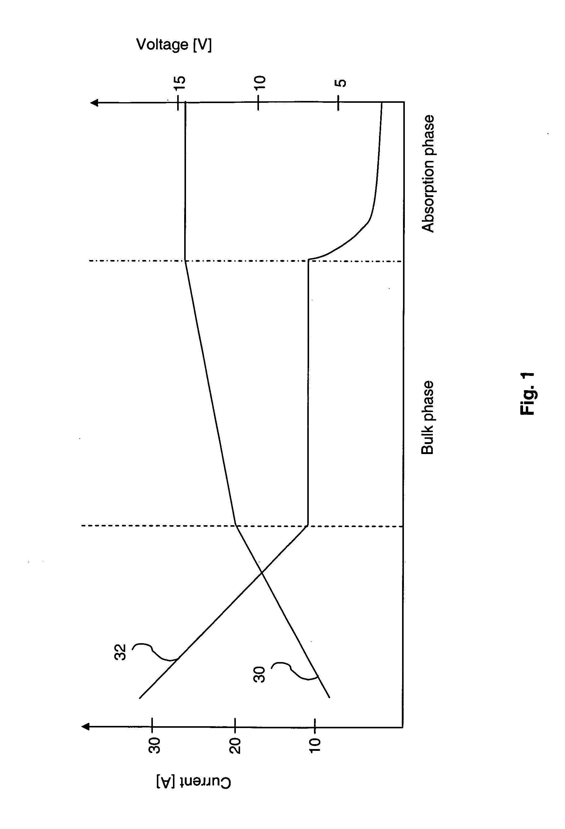
[0013] The present invention is based on the idea of utilizing connection means, such as diodes or relays, for high generator currents and DC / DC converters when the battery voltage has increased and, accordingly, the current has dropped. Thereby, an efficient separation and charging of the batteries can be obtained. For example, the tendency of levelling out imbalances leading to that the least charged battery pulling down the other can be avoided. Moreover, the potential risk that a defective battery depletes the healthier one to the point where both are useless is more or less eliminated. In addition, an individual charging of the connected batteries can be obtained and an efficient charging of the battery can be obtained. The invention can also be used in a wide variety of different types of batteries, for example, lead-acid batteries NiCd batteries, Lilon batteries, or NiMH batteries. Moreover, it can handle a very broad spectrum of currents. The design of the present invention is simple and can therefore be realised in a cost effective manner.
[0016] According to a further embodiment of the present invention, the control means is arranged to communicate with the first and / or second DC / DC converter via the communication bus, the control means being adapted to control function of the first and / or second DC / DC converter. Thereby, the charging procedure of the battery or batteries can be controlled in an even more effective way.

Problems solved by technology

Generators of, for example, boats, vehicles, such as cars or heavy trucks, or caravans do not charge the battery to full capacity due to the fact that they normally charge at a too low voltage.
A voltage of about 13,5-14 V of the generator is not sufficient for an efficient charging of the battery.
In addition, there is often a voltage drop over the connection wires, in particular, in boats and caravans where long connection wires are used.
Unfortunately such generators are very expensive and have a complex construction.
This booster is not capable of handling the generator current over the complete charging spectra, in particular, generator currents over 40-50 A.
Unfortunately, multi-battery installations bring their own charging problems.
Obviously, both batteries must be charged from the same source (the alternator), and if they remain connected once the charging current has stopped, any imbalance in charge between the two will tend to level out, with the least charged battery pulling down the other.
If one of the batteries were to become defective, it could deplete the healthier one to the point where both could be useless.
However, this arrangement is inherently prone to forgetfulness since the user, for example, has to remember to switch to the engine battery before starting the engine and switch back to the service battery after the engine has been running for while.
However, this solution is impaired with the disadvantage that the voltage drops over the diodes entail that the charging voltage of the batteries will be too low.
Moreover, there is no individual treatment of the batteries, which may cause overcharging and / or an erroneous charging.
However, these electronic separating means are very expensive.

Method used


Image

  • Battery charging device
  • Battery charging device
  • Battery charging device

Examples


first embodiment

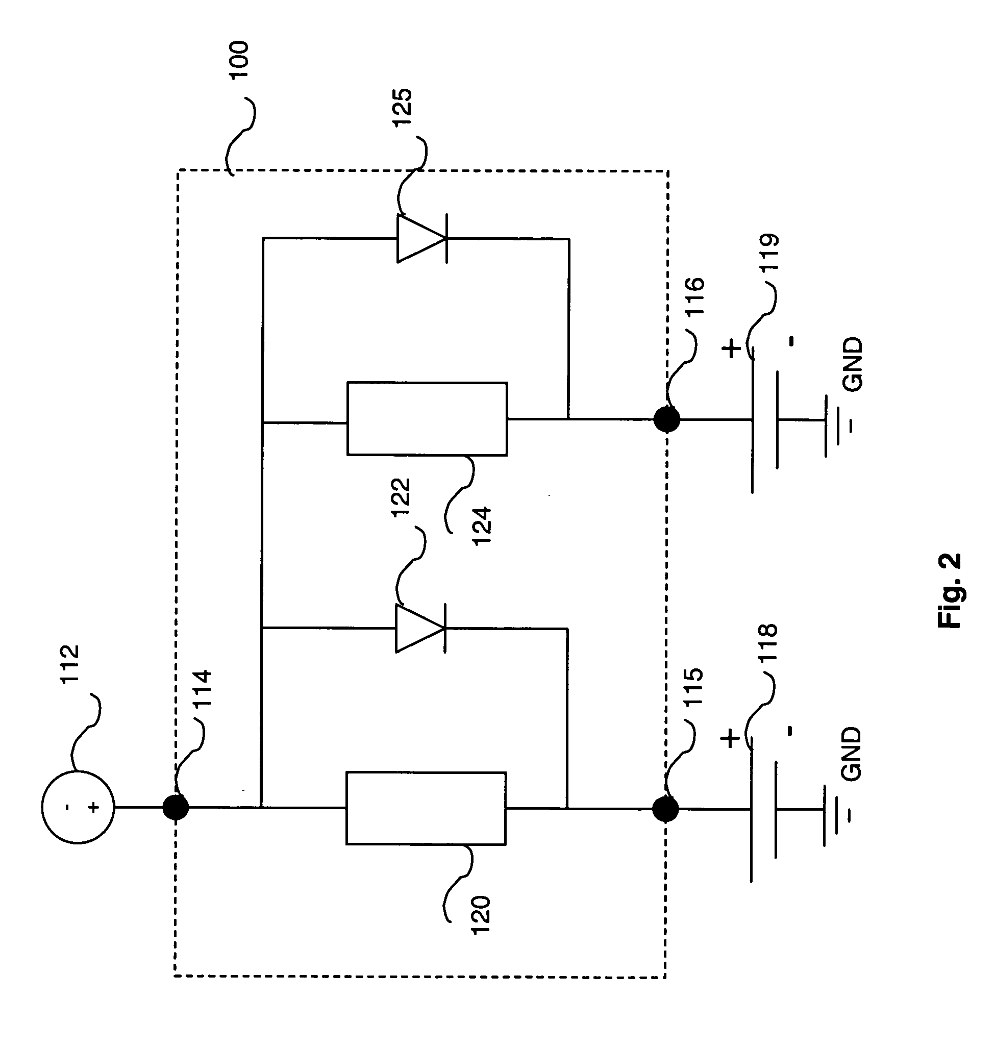
[0034] Referring first to FIG. 2, the battery charging device according to the present invention will be described. The battery charging device 100 is connectable to a alternating voltage generating device 112, such as a generator, alternator or other type of charging device, at an input terminal 114. At a first output terminal 115, the system 100 is connectable to a first battery 118, and at a second output terminal 116 the system 100 is connectable to a second battery 119. For example, the first battery 118 may be a supply battery and the second battery 119 may be a starter battery. The battery charging device 100 comprises a first DC / DC converter 120 arranged between the first input terminal 114 and the first output terminal 115. In a preferred embodiment, the first DC / DC converter 120 is adapted to supply a controlled charging curve and to handle a current in the range of 1-25 A. Furthermore, a first connection means 122 is arranged in parallel with the first DC / DC converter 120...

second embodiment

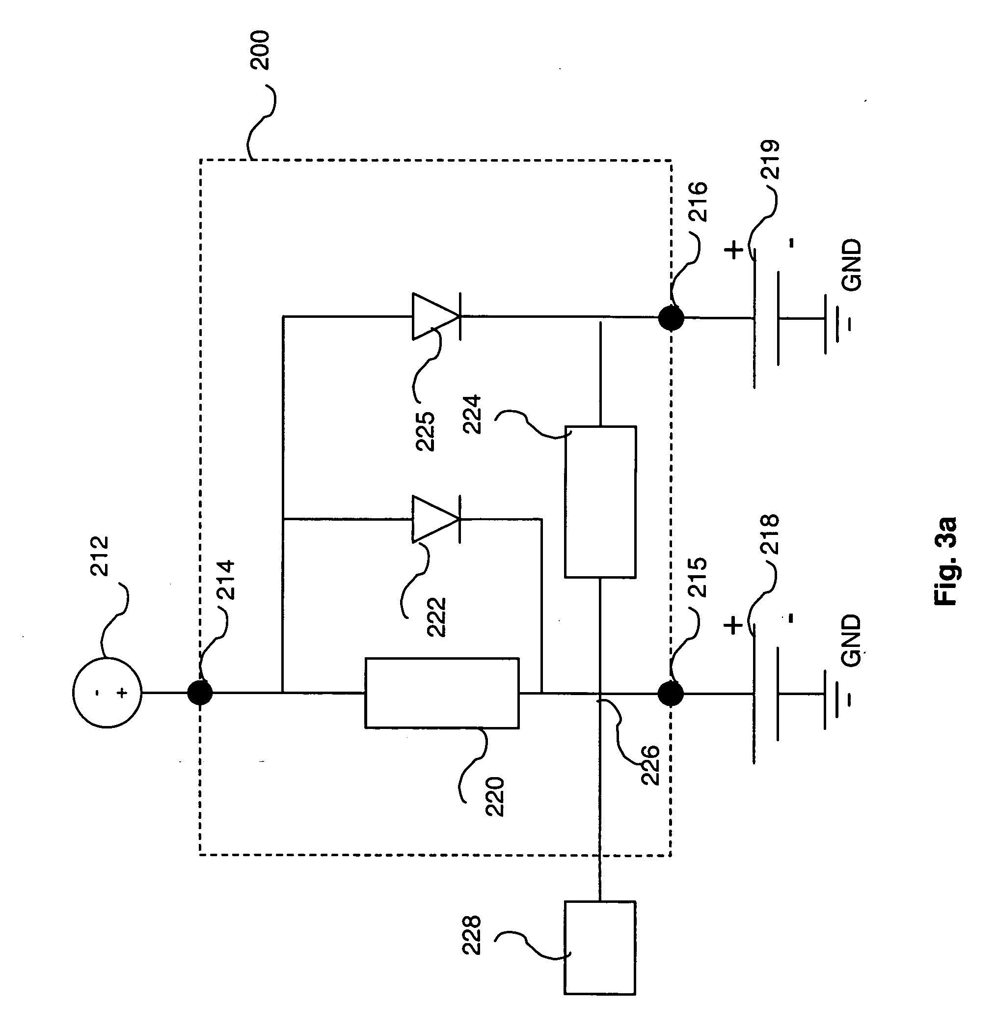
[0037] With reference now to FIG. 3a, the battery charging device according to the present invention will be described. The battery charging device 200 is connectable to an alternating voltage generating device 212, such as a generator, alternator or other type of charging device, at an input terminal 214. At a first output terminal 215, the system 200 is connectable to a first battery 218, and at a second output terminal 216 the system 200 is connectable to a second battery 219. For example, the first battery 218 may be a supply battery and the second battery 219 may be a starter battery. The battery charging device 200 comprises a first DC / DC converter 220 arranged between the first input terminal 214 and the first output terminal 215. In a preferred embodiment, the first DC / DC converter 220 is adapted to supply a controlled charging curve and to handle a current in the range of 1-25 A. Furthermore, a first connection means 222 is arranged in parallel with the first DC / DC converte...

fifth embodiment

[0043] Turning now to FIG. 4, the battery charging device according to the present invention will be described. The battery charging device 300 is connectable to an alternating voltage generating device 312, such as a generator, alternator or other type of charging device, at an input terminal 314. At a first output terminal 315, the system 300 is connectable to a first battery 318, and at a second output terminal 316 the system 300 is connectable to a second battery 319. For example, the first battery 318 may be a supply battery and the second battery 319 may be a starter battery. The battery charging device 300 comprises a first DC / DC converter 320 arranged between the first input terminal 314 and the first output terminal 315. In a preferred embodiment, the first DC / DC converter 320 is adapted to supply a controlled charging curve and to handle a current in the range of 1-25 A. Furthermore, a first connection means 322 is arranged in parallel with the first DC / DC converter 320. P...


PUM


Abstract

A battery charging device comprising a first DC / DC converter being adapted to increase a voltage of a battery; a first connection means coupled in parallel with the first DC / DC converter; wherein current delivered from the generator is supplied to the battery via the first connection means at a current level above a current level and wherein current delivered from the generator is supplied to the battery via the DC / DC converter at a current level below the current level; and a second DC / DC converter adapted to increase a voltage of a second battery, wherein the current delivered from the generator is supplied to the second battery via the second DC / DC converter.

Description

[0001] This application claims priority to patent application number 0500797-6, filed in Sweden on Apr. 8, 2005, the contents of which are incorporated herein by reference in its entirety. TECHNICAL FIELD [0002] The present invention relates to a battery charging device for isolating batteries being charged from a single source (e.g. an alternator) that can be manufactured at a low cost, and that can be used in wide variety of applications, such as, cars, buses, boats, or caravans. BACKGROUND OF THE INVENTION [0003] Generators of, for example, boats, vehicles, such as cars or heavy trucks, or caravans do not charge the battery to full capacity due to the fact that they normally charge at a too low voltage. A voltage of about 13,5-14 V of the generator is not sufficient for an efficient charging of the battery. In addition, there is often a voltage drop over the connection wires, in particular, in boats and caravans where long connection wires are used. Traditionally, these problems ...

Claims


Application Information

Patent Timeline
IPC IPC(8): H02J7/00
CPCH02J7/1423H02J7/0018H02J7/008H02J7/022
Inventor MALEUS, BORJE
Owner CREATOR TEKNISK UTVECKLING
Learn More