Controlling polarization for liquid crystal displays

a liquid crystal display and control polarization technology, applied in non-linear optics, instruments, optics, etc., can solve the problems of high difficulty in providing a sunlight readable display system integrated with emi, inconvenient outdoor applications, touch panel, etc., and achieves low reflection and increased contrast and brightness.

Inactive Publication Date: 2006-11-23
WANG RAN HONG RAYMOND +1
View PDF12 Cites 95 Cited by
  • Summary
  • Abstract
  • Description
  • Claims
  • Application Information

AI Technical Summary

Benefits of technology

[0004] Certain embodiments of liquid crystal displays and liquid crystal display functional parts have low reflection for outdoor applications and also have the advantage of being able to provide increased contrast and brightness for certain convenient viewing directions for outdoor viewers wearing polarized sunglasses.

Problems solved by technology

Thus, providing a sunlight readable display system integrated with EMI, IR block, touch panel, and screen heater becomes highly challenging.
However, the reflection problem is still a concern when it comes to a system integrated with multiple functional parts comprising conductive films, since the reflections of each functional part are additive and become significant.
A conventional liquid crystal display or a liquid crystal display with a polarized touch screen that emits linearly polarized light would thus appear to be black for viewers wearing polarized sunglasses for common viewing directions, which is inconvenient for outdoor applications.

Method used


Image

  • Controlling polarization for liquid crystal displays
  • Controlling polarization for liquid crystal displays
  • Controlling polarization for liquid crystal displays

Examples


example 1

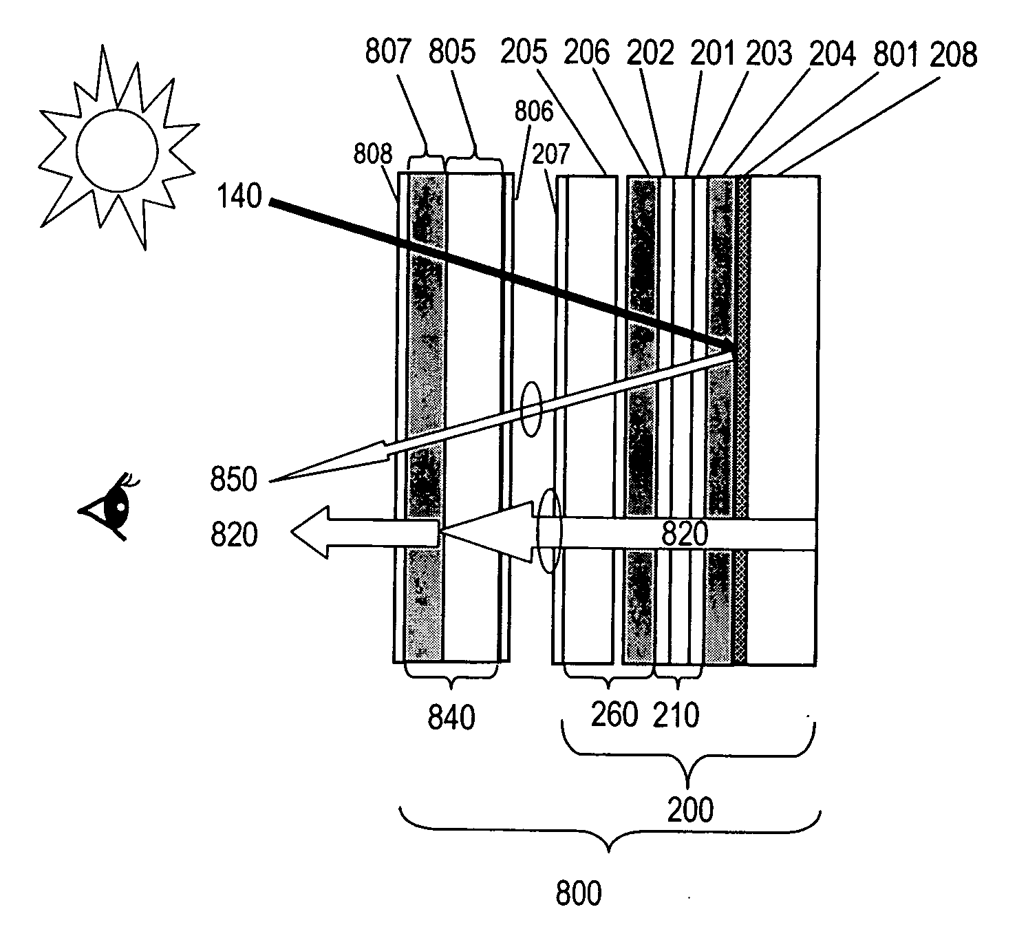
[0093] A 10.4″ NLP-LCD with right-handed circular polarization output was tested and demonstrates no dark viewing zones for viewers wearing polarized sunglasses.

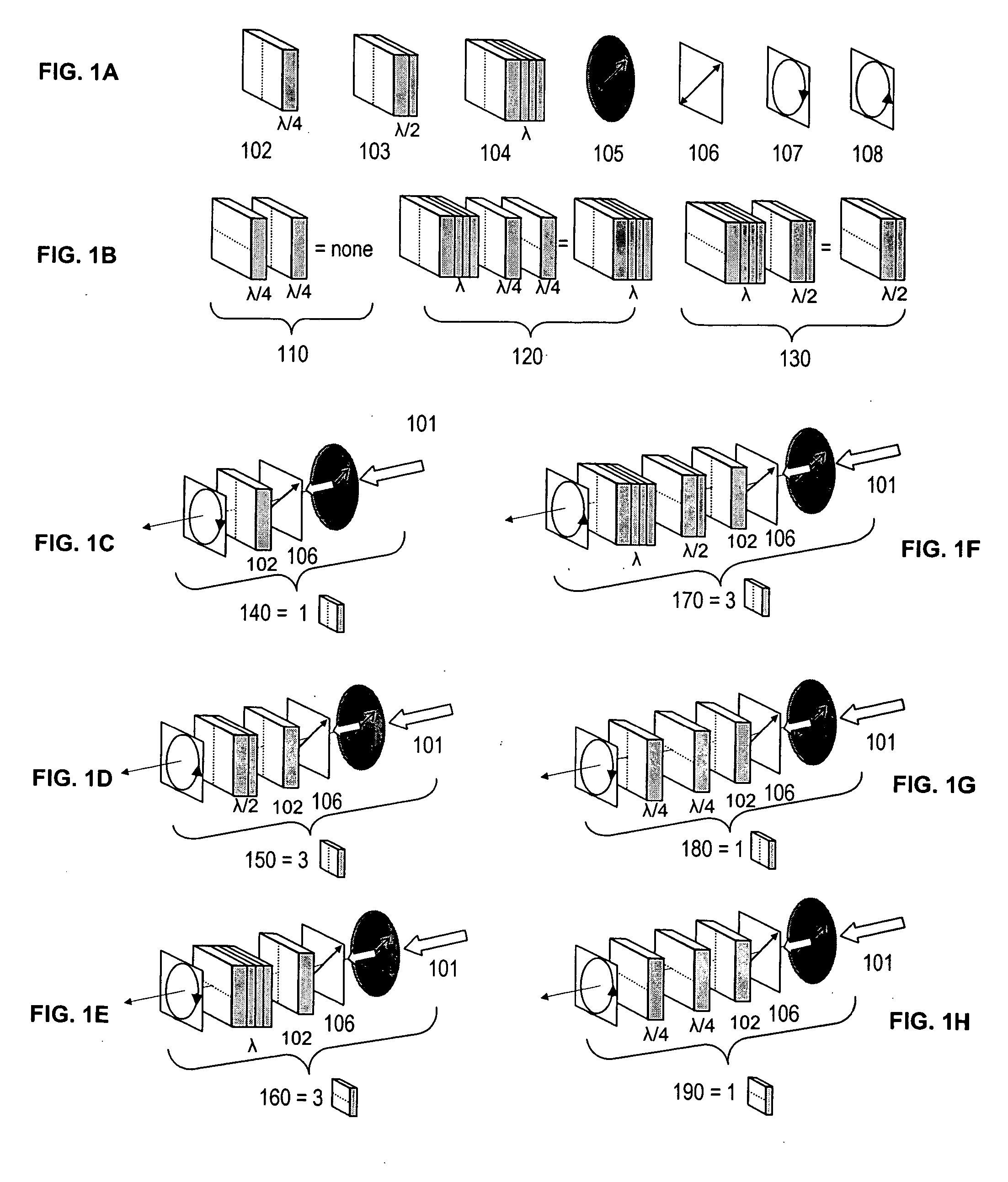
[0094] In comparison, an 10.4″ LCD with 45 degree linear polarization output with 200 nits measured brightness, shows dark viewing zones in directions of about 1:00 and 7:00 o'clock when viewed with polarized sunglasses on. This LCD was converted to an NLP-LCD with right-handed circular polarization output by laminating a quarter wave retardation film, 65 um in thickness, with its slow axis oriented at an angle of −45 degree with respect to the linear polarization of the LCD. The brightness of the converted LCD was measured as 185 nits and showed no dark viewing zones when viewed with polarized sunglasses on.

example 2

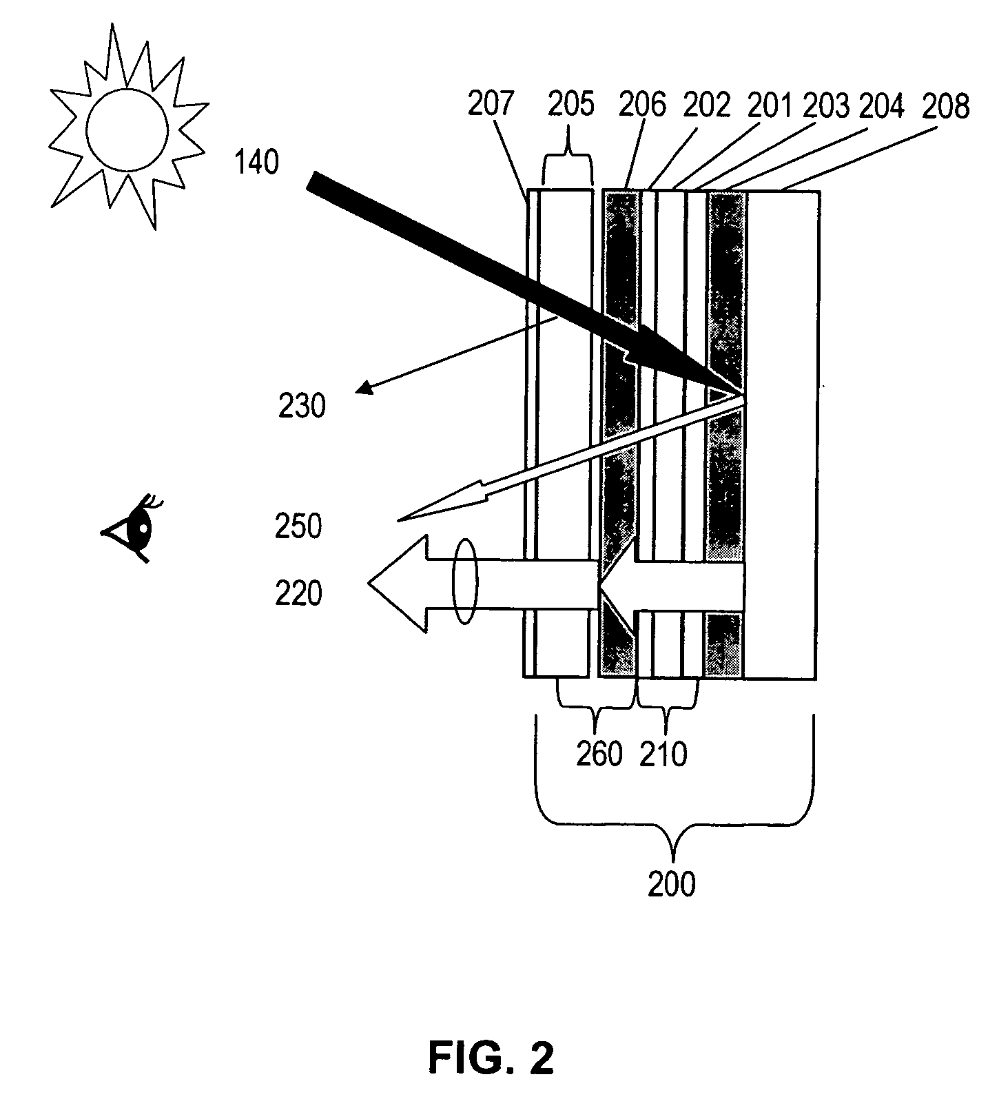
[0095] A 10.4″ NLP-LCD integrated with a polarized resistive touch panel shows no limitation on the orientation of the second circularly polarizing plate on the touch panel. The second right-handed circularly polarizing plates were prepared by laminating together a quarter wave plate retarder described in Example 1 and a linear polarizer having a thickness of 100 um, a transmission ˜43%, and a polarization coefficient —96% . The second right-handed circular polarizer was laminated in various orientations on a 5-wired 10.4″ resistive touch panel (82% transmission) to generate low reflection polarized touch panels. The low reflection polarized touch panel with various orientation of the second linear polarization axis was then disposed on the NLP-LCD generated as described in Example 1. Brightness of light output was measured. The brightness measured and the various orientations of the polarization axis are summarized below:

Orientation of theBrightness (nits) of the lightsecond line...


PUM


Abstract

Certain embodiments of liquid crystal displays and liquid crystal display functional parts have low reflection for outdoor applications and also have the advantage of being able to provide increased contrast and brightness for certain convenient viewing directions for outdoor viewers wearing polarized sunglasses.

Description

FILED OF INVENTION [0001] The present invention relates to liquid crystal displays and polarization. DESCRIPTION OF RELATED TECHNOLOGY [0002] Many features of liquid crystal displays (LCDs), such as light weight, compact dimensions, low power consumption and high resolution, make LCDs popular choices in various outdoor electronic applications, including for PDAs, navigation systems, rugged notebooks, and information terminals. Thus, the readability of LCD displays in sunlight is desirable in these outdoor applications. The above-mentioned devices are also often integrated with multiple functional parts, such as a resistive touch panel, EMI shield, IR block, and screen heater. However, these functional parts are highly reflective, ˜20%, due to the conductive films contained therein. Thus, providing a sunlight readable display system integrated with EMI, IR block, touch panel, and screen heater becomes highly challenging. [0003] Adding lamps to the backlight cell to increase LCD's ill...

Claims


Application Information

Patent Timeline
Patent Type & Authority Applications(United States)
IPC IPC(8): G02F1/1335
CPCG02F2001/133638G02F1/133555G02F1/133638
Inventor WANG, RAN-HONG RAYMONDWANG, MIN-SHINE CHOW
Owner WANG RAN HONG RAYMOND
Why Eureka
Try Eureka