

X-ray device with an x-ray source fixed to a ceiling stand
- Summary
- Abstract
- Description
- Claims
- Application Information
AI Technical Summary
Benefits of technology
Problems solved by technology
Method used
Image

Examples
Embodiment Construction
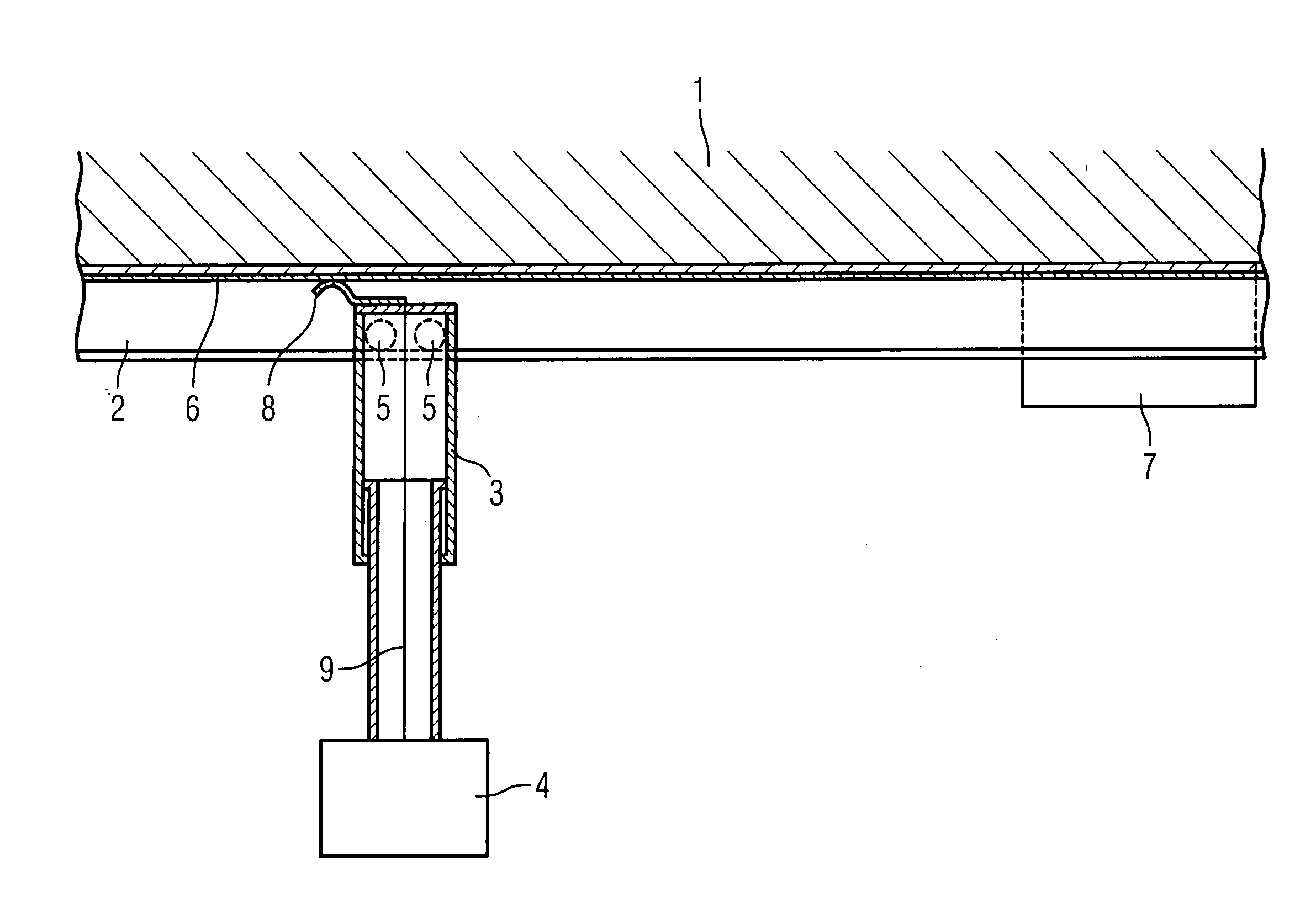
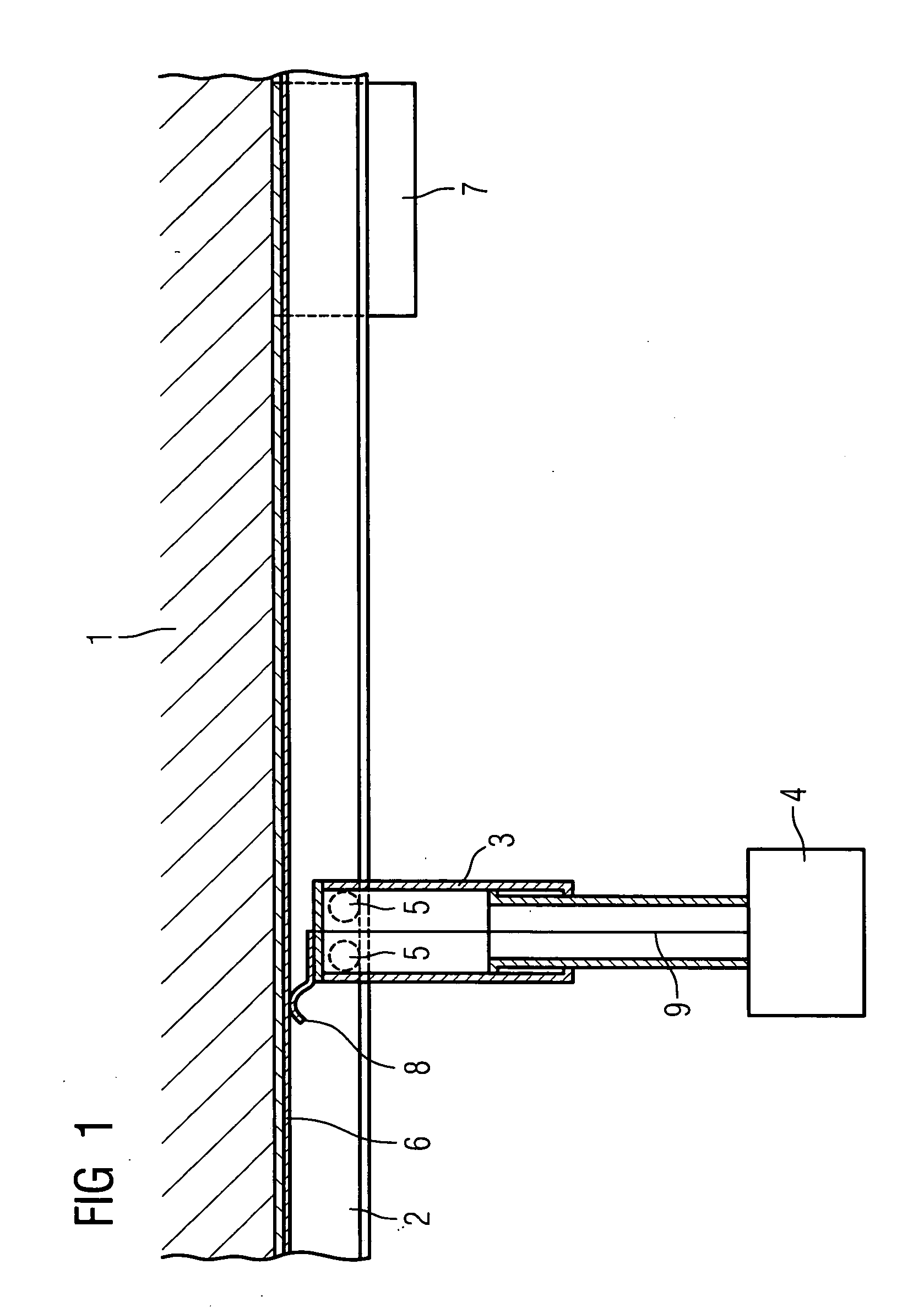
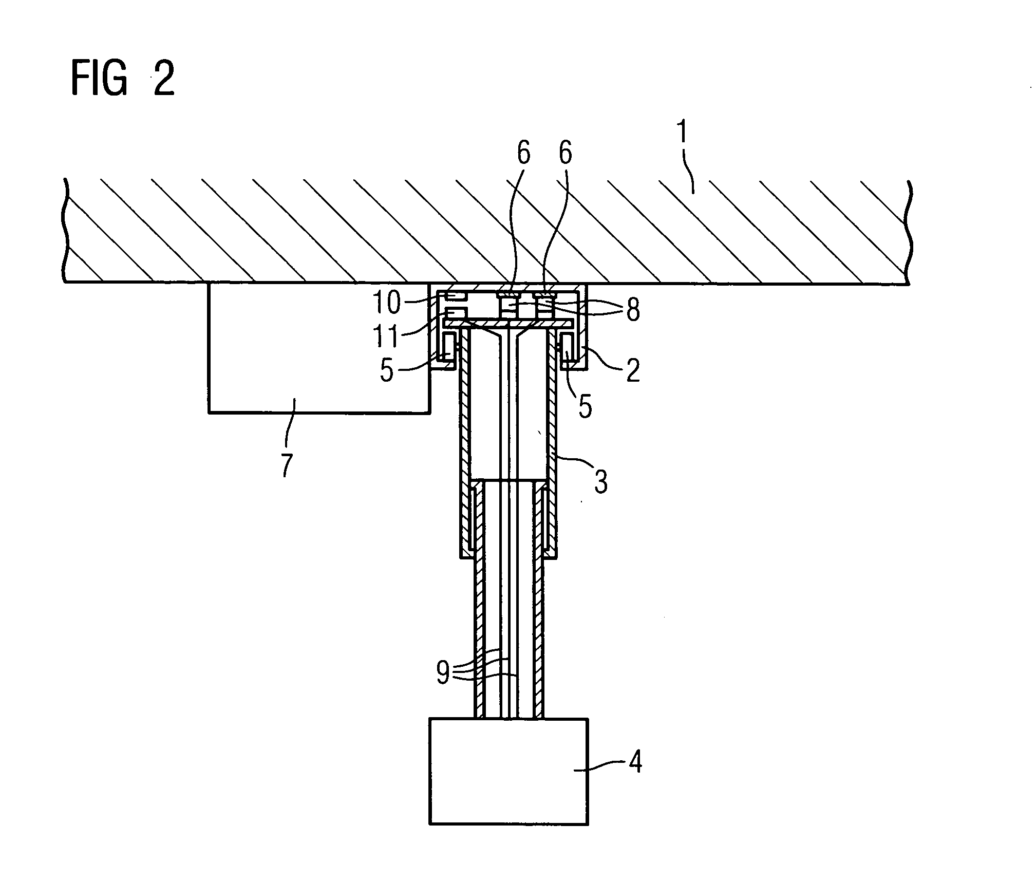
[0019] With the x-ray device shown in FIGS. 1 and 2, a guide rail 2 is fixed to a ceiling 1, along which guide rail a ceiling stand 2 can be moved which is preferably designed to be telescopable. An x-ray source 4, shown here schematically, is fixed to the end of the ceiling stand 3. The guide rail 2 can be designed according to a type of U-profile, with further U-profiles pointing inwards being fixed in turn to the two sides of the U-profile, said further U-profiles serving as tracks for rollers 5 fixed to the ceiling stand 3. Two conductor rails 6, which are connected to a generator 7 in an electrically conductive manner, are fixed to a base plate of the U-profile between the sides of the guide rail 3, preferably interconnecting with an electrically insulating layer (not shown here). Sliding contacts 8 are provided on the ceiling stand 3 corresponding to the conductor rails 6, said sliding contacts 8 being pushed against the conductor rails 6 using a spring-biased force. The slidi...
PUM
 Abstract
Description
Claims
Application Information