
Multilumen catheter for minimizing limb ischemia

a multi-lumen catheter and limb technology, applied in the field of multi-lumen catheters, can solve the problems of increasing the potential for infection and other complications, complex reactions within the body, and sometimes adverse reactions, and achieve the effect of maintaining or enhancing perfusion

Inactive Publication Date: 2006-11-23
TC1 LLC
View PDF99 Cites 21 Cited by
  • Summary
  • Abstract
  • Description
  • Claims
  • Application Information

AI Technical Summary

Benefits of technology

The present invention is a multilumen catheter that allows for the direct flow of blood to and from a patient through a single cannulation site. The catheter has multiple lumens with apertures that can be positioned to enhance perfusion of blood to the patient's vasculature. The catheter can also have a redirecting tip to direct blood flow in a different direction. The invention also includes a connector and a pump for circulating blood through the patient. The method of using the catheter involves inserting it into a patient at a single cannulation site, withdrawing blood from one of the blood vessels, and delivering blood through the other lumen so that blood is delivered upstream and downstream of the cannulation site. The technical effects of the invention include improved blood flow and perfusion, reduced risk of complications, and improved patient outcomes.

Problems solved by technology

Still, insertion of a cannula into the circulatory system can cause complex, and sometimes adverse, reactions within the body.
One problem with using two single lumen catheters is that it subjects the patient to multiple percutaneous insertion procedures, which complicates the procedure and increases the potential for infection and other complications.
While multilumen catheters require only a single puncture of the epidermis, their performance is limited in at least two ways.
This has the potential to cause damage to the vessel as blood comes jetting out of the return lumen.
Also, it may put further stress upon blood cells, even causing hemolysis.
As a result, limited blood supply reaches tissues and organs located downstream of the catheter in the vascular system.
With insufficient perfusion, the tissues downstream of the lumen insertion site suffer from ischemia and become oxygen deprived.
Prolonged oxygen deprivation can lead to tissue damage, as is well known in the art.

Method used


Image

  • Multilumen catheter for minimizing limb ischemia
  • Multilumen catheter for minimizing limb ischemia
  • Multilumen catheter for minimizing limb ischemia

Examples


Embodiment Construction

[0031] Turning now to the drawings provided herein, a more detailed description of the embodiments of the present invention is provided below.

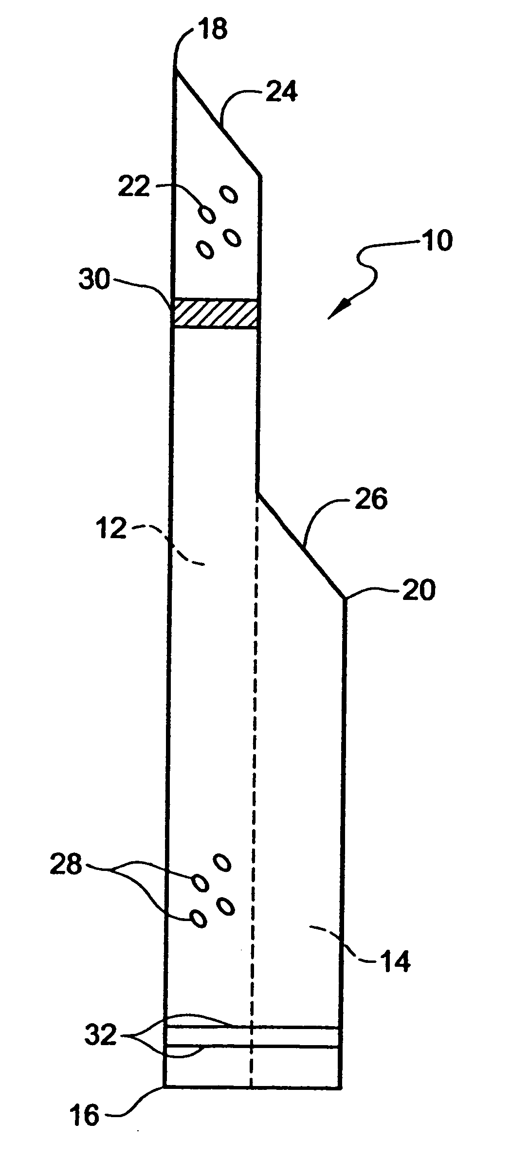
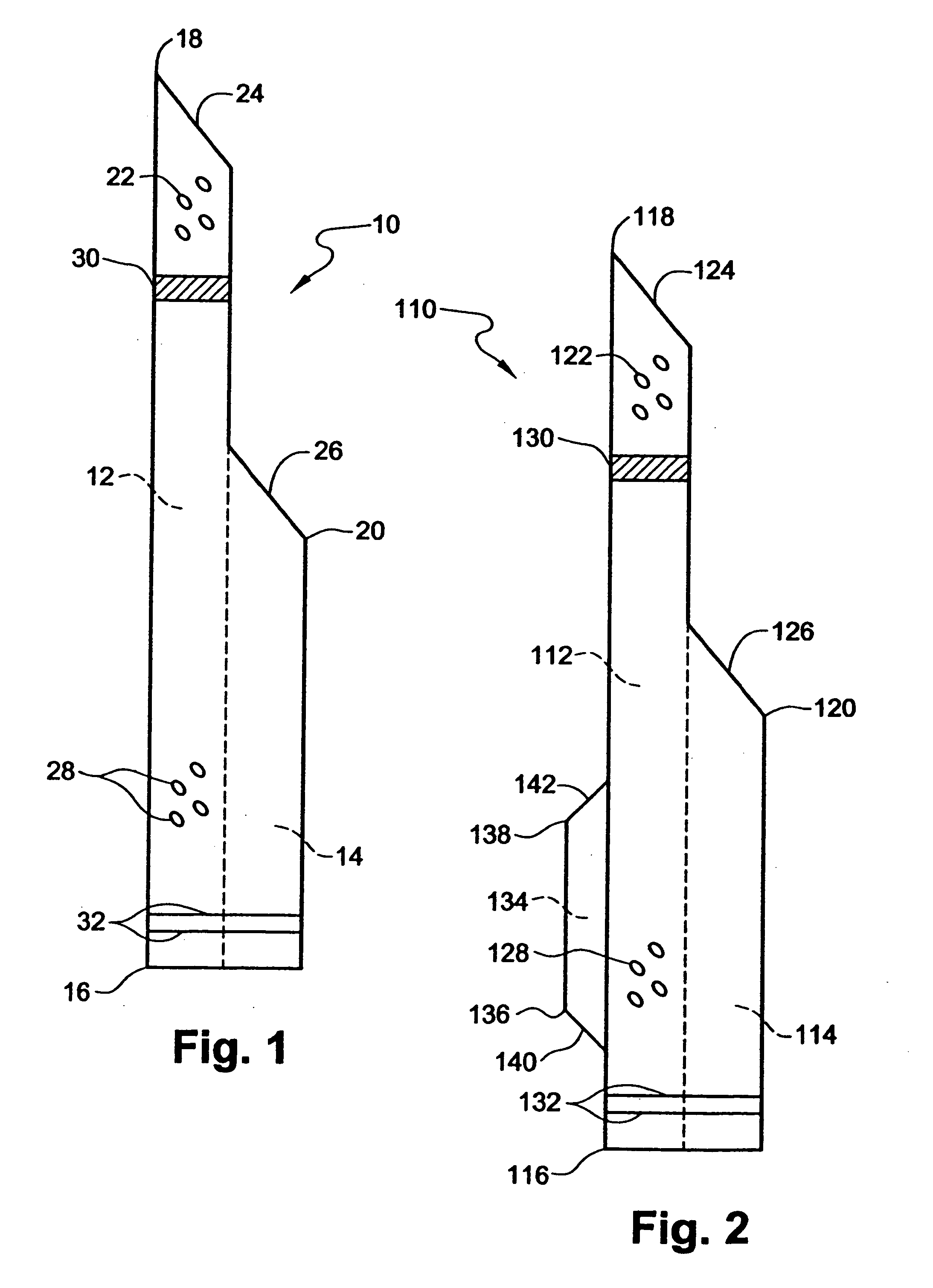
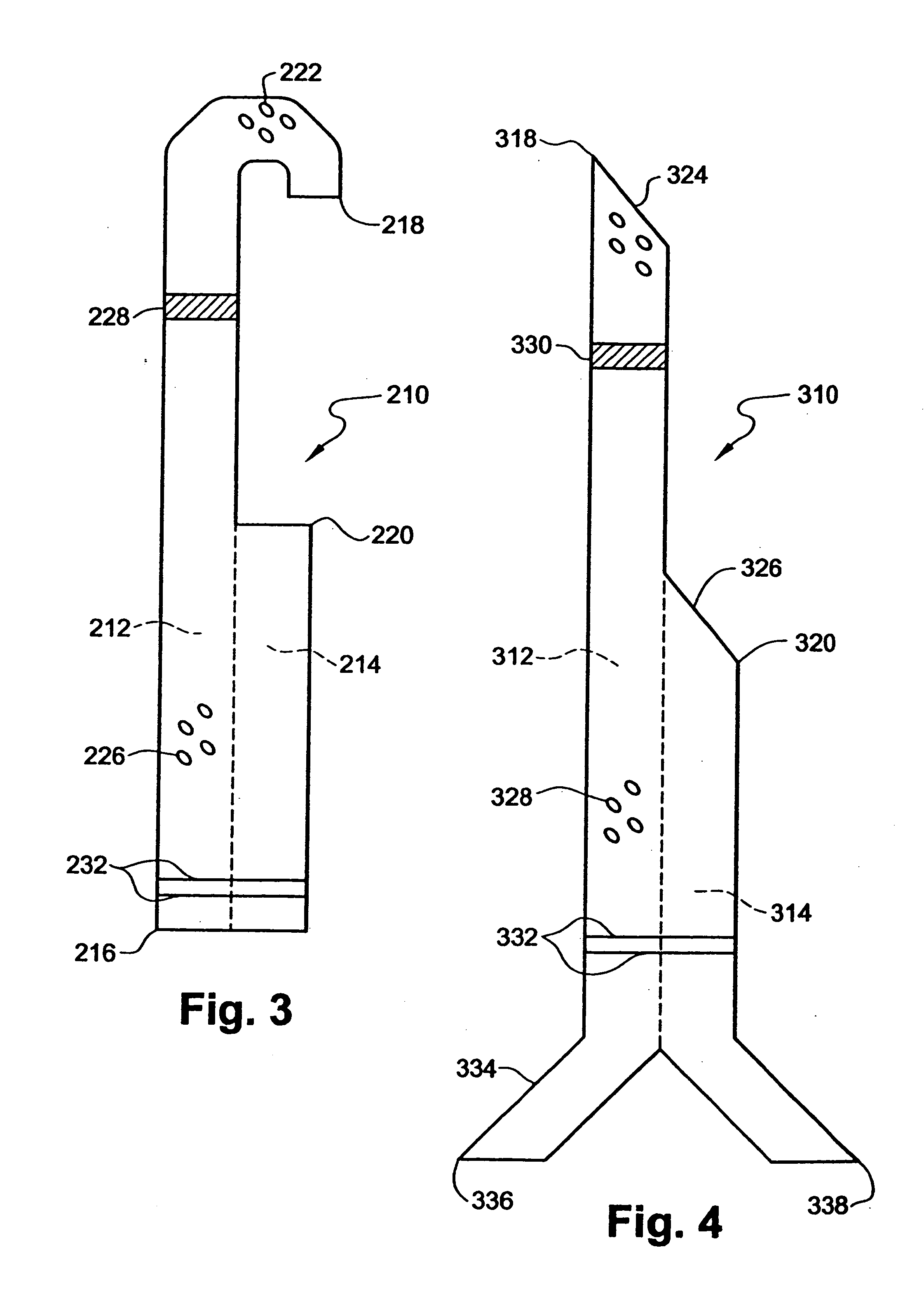
[0032] With reference to FIG. 1, one embodiment of the present invention comprises a multilumen catheter 10 designed to lessen ischemia that can occur when a large diameter catheter is inserted into a patient's blood vessel. The multilumen catheter preferably is of unitary construction and requires only one entry point into the patient's body. The multilumen catheter 10 comprises at least two lumens: a first lumen 12 and a second lumen 14. The first lumen 12 extends from a proximal end 16 of the multilumen catheter 10 to a first distal end 18. The second lumen 14 extends from the proximal end 16 of the multilumen catheter 10 to a second distal end 20. The lumens 12, 14 of the multilumen catheter 10 may be arranged one of many different ways. For example, the two lumens may be joined in a side-by-side manner, forming a “figure-8” when viewed f...


PUM


Abstract

A multilumen catheter that maximizes the blood flow into and out of the patient's vasculature while also providing for passive and / or active perfusion of tissue downstream of where the catheter resides in the vasculature. The inventive catheter comprises a proximal end, a first distal and a second distal end with first and second lumens extending from the proximal end to each of these distal ends to provide for blood circulation within one blood vessel or between two different blood vessels. The second lumen, and any additional lumens so desired, may be positioned coaxially with or radially around the first lumen. Redirecting means is provided at a distal end of at least one of said lumens for directing blood in a direction generally opposite of the direction of flow through said lumen.

Description

RELATED APPLICATIONS [0001] This application is a divisional of U.S. application Ser. No. 10 / 078,283, filed Feb. 14, 2002, which is a continuation-in-part of U.S. application Ser. No. 09 / 876,281, filed Jun. 6, 2001, both of which are incorporated herein in their entireties by reference.BACKGROUND OF THE INVENTION [0002] 1. Field of the Invention [0003] The present invention relates to a multilumen catheter and, in particular, to multilumen catheters designed to prevent ischemia in patients when the catheter is positioned within the body. [0004] 2. Description of the Related Art [0005] It is often necessary to divert the flow of blood from a patient's blood vessel back to the same or a different blood vessel as part of treating a patient suffering from one or more of numerous health impairments, including cardiovascular disease, such as congestive heart failure. Although surgical cut-down procedures can achieve this, percutaneous insertion of catheters has made this procedure less in...

Claims


Application Information

Patent Timeline
Patent Type & Authority Applications(United States)
IPC IPC(8): A61M36/00A61M1/12A61M1/36A61M25/00A61M25/14A61M25/16
CPCA61M1/3653A61M25/003A61M25/0068A61M25/007A61M2025/0031A61M1/3659A61M2025/0039A61M2025/1095A61M1/122A61M1/3613A61M2025/0037A61M25/0071A61M2025/0025A61M2025/0073A61M60/148A61M60/857A61M60/205A61M60/152A61M60/867A61M25/00
Inventor VIOLE, ANTHONYSIRIMANNE, LAKSENBOLLING, STEVEN F.O'LEARY, SHAWNPECOR, ROBERTKELLY, RYANWERNER, WOLFGANGBEIZAI, MASOUD
Owner TC1 LLC
Learn More