Portal design for stent for treating bifurcated vessels

a bifurcation and port design technology, applied in the field of vascular repair devices, can solve the problems of affecting the repair of bifurcations that are particularly challenging, and affecting the repair of bifurcations

Inactive Publication Date: 2006-11-23
ABBOTT CARDIOVASCULAR
View PDF54 Cites 30 Cited by
  • Summary
  • Abstract
  • Description
  • Claims
  • Application Information

AI Technical Summary

Benefits of technology

[0013] The stent of the present invention includes a cylindrical body having a proximal opening, a distal opening, and a central (portal) opening. The distal opening and the proximal opening are aligned along the stent longitudinal axis and typically would be implanted in the main vessel, while the central opening is radially offset relative to the alignment of the distal opening and the proximal opening. The stent is implanted so that the central opening provides access to the side branch (or alternative vessel) and the ring or rings proximal to the central opening provide support and coverage to the origin of the side branch and to the area immediately proximal to the carina. The cylindrical body of the stent includes a plurality of rings aligned along a longitudinal axis, where each ring has a delivery diameter in which it is crimped or compressed tightly onto the balloon catheter, and an implanted diameter where the stent is implanted in a bifurcated vessel. Each ring also includes a number of first peaks that are configured to spread apart to permit the rings to be greatly expanded outwardly or to be compressed radially inwardly onto the balloon portion of a delivery catheter.

Problems solved by technology

Repair of vessels that are diseased at a bifurcation is particularly challenging since the stent must be precisely positioned, provide adequate coverage of the diseased area, provide access to any diseased area located distal to the bifurcation, and maintain vessel patency in order to allow adequate blood flow to reach the myocardium.
Where the stent provides coverage to the vessel at the diseased portion, yet extends into the vessel lumen at the bifurcation, the diseased area is repaired, but blood flow may be compromised in other portions of the bifurcation.
Unapposed stent elements may promote lumen compromise during neointimal formation and healing, producing restenosis and requiring further procedures.
Moreover, by extending into the vessel lumen at the bifurcation, the stent may block access to further interventional procedures.
Conventional stents are designed to repair areas of blood vessels that are removed from bifurcations, and, therefore are associated with a variety of problems when attempting to use them to treat lesions at a bifurcation.
The drawback with this approach is that there is no way to determine or guarantee that the main vessel stent struts are properly oriented with respect to the side branch or that an appropriate stent cell has been selected by the wire for dilatation.
The aperture created often does not provide a clear opening and creates a major distortion in the surrounding stent struts.
A further drawback with this approach is that there is no way to tell if the main vessel stent struts have been properly oriented and spread apart to provide a clear opening for stenting the side branch vessel.
This technique also causes stent deformation to occur in the area adjacent to the carina, pulling the stent away from the vessel wall and partially obstructing flow in the originally non jailed vessel.
Deforming the stent struts to regain access into the previously jailed strut is also a complicated and time consuming procedure associated with attendant risks to the patient and is typically performed only if considered an absolute necessity.
The risks of procedural complications during this subsequent deformation are considerably higher than stenting in normal vessels.
The inability to place a guide wire through the jailed lumen in a timely fashion could restrict blood supply and begin to precipitate symptoms of angina or even cardiac arrest.
In addition, platelet agitation and subsequent thrombus formation at the jailed site could further compromise blood flow into the side branch.
This procedure is also associated with the same issues and risks previously described when stenting only one vessel and deforming the struts through the jailed vessel.
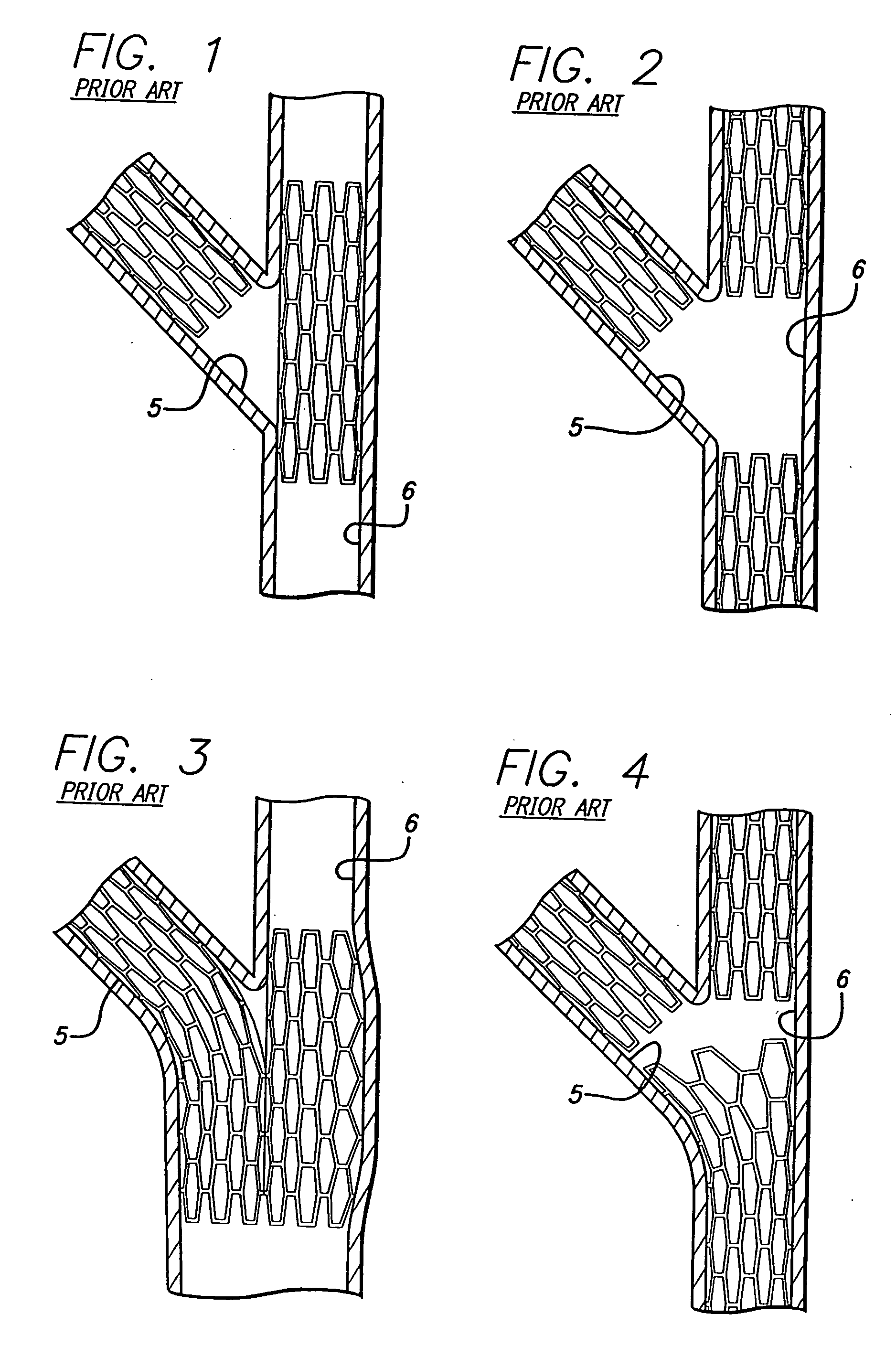
In addition, since a conventional stent generally terminates at right angles to its longitudinal axis, the use of conventional stents to treat the origin of the previously jailed vessel (typically the side branch vessel) may result in blocking blood flow of the originally non-jailed vessel (typically the parent vessel) or fail to provide adequate coverage of the disease in the previously jailed vessel (typically a side branch vessel).
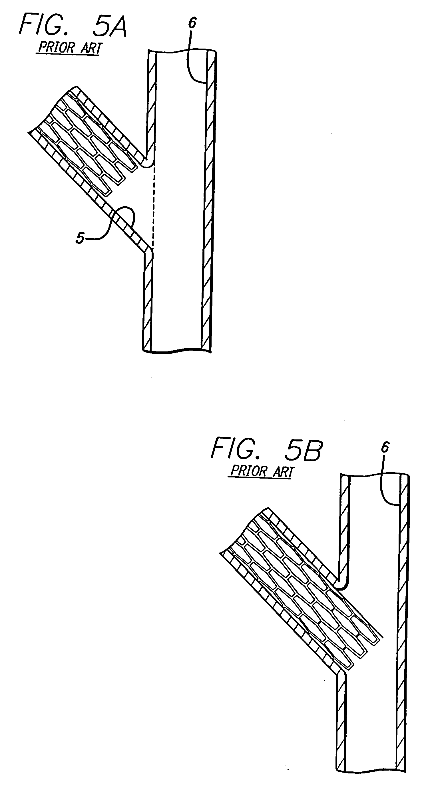
Such a position of the conventional stent results in a bifurcation that does not provide full coverage or has a gap on the proximal side (the origin of the side branch) of the vessel and is thus not completely repaired.
One of the drawbacks of this approach is that the orientation of the stent elements protruding from the side branch vessel into the main vessel is completely random.
In addition excessive metal coverage exists from overlapping strut elements in the parent vessel proximal to the carina area.
When dilating the main vessel the stent struts are randomly stretched, thereby leaving the possibility of restricted access, incomplete lumen dilatation, and major stent distortion.
All of the foregoing stent deployment assemblies suffer from the same problems and limitations.
Typically, there are uncovered intimal surface segments on the main vessel and side branch vessels between the stented segments or there is excessive coverage in the parent vessel proximal to the bifurcation.
An uncovered flap or fold in the intima or plaque will invite a “snowplow” effect, representing a substantial risk for subacute thrombosis, and the increased risk of the development of restenosis.
Further, where portions of the stent are left unapposed within the lumen, the risk for subacute thrombosis or the development of restenosis again is increased.
The prior art stents and delivery assemblies for treating bifurcations are difficult to use and deliver making successful placement nearly impossible.
Even where placement has been successful, the side branch vessel can be “jailed” or covered so that there is impaired access to the stented area for subsequent intervention.
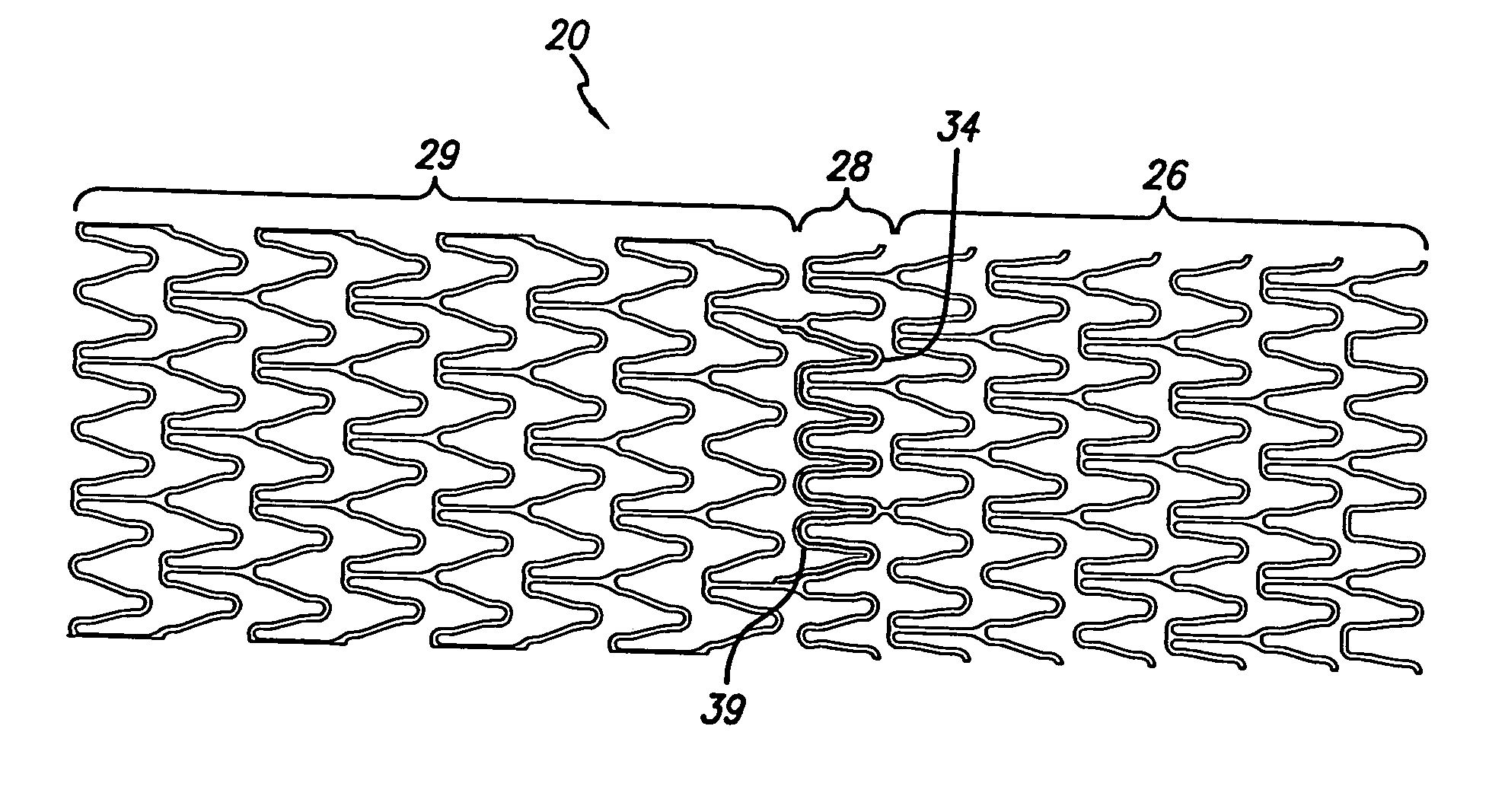
Further, even with the various patterns of the portal region of a currently manufactured type of bifurcated stent, there is a tendency of the ring or rings of the portal region to immediately overlap with an adjacent ring of the proximal section during stent deployment.

Method used


Image

  • Portal design for stent for treating bifurcated vessels
  • Portal design for stent for treating bifurcated vessels
  • Portal design for stent for treating bifurcated vessels

Examples


Embodiment Construction

[0048] The present invention is directed to improved stent patterns for the portal region of a stent in the treatment of a bifurcation in the coronary arteries, veins, peripheral vessels, and other body lumens. Prior art attempts at implanting intravascular stents in a bifurcation have proved less than satisfactory. For example, FIGS. 1-4 depict prior art devices which include multiple stents being implanted in both the main vessel and a side branch vessel. In FIG. 1, a prior art “T” stent is implanted such that a first stent is implanted in the side branch near the origin of the bifurcation, and a second stent is implanted in the main vessel, into the side branch. With this approach, portions of the side branch vessel are left uncovered, and blood flow to the side branch vessel must necessarily pass through the main vessel stent, causing possible obstructions or thrombosis.

[0049] Referring to FIG. 2, three prior art stents are required to stent the bifurcation. In FIG. 3, the prio...


PUM


Abstract

A stent pattern includes an improved portal region for repairing a main vessel and a side branch vessel forming a bifurcation. More particularly, the stent has rings aligned along a common longitudinal axis that are connected by links, where the stent has a proximal section, a distal section, and a central section (portal region). The number of rings and the expanded diameter of the sections are varied to create a “trap door” capable of expanding to a slightly larger diameter than the proximal section and the distal section of the stent. The configuration of the stent pattern of the portal region prevents the occurrence of portal overlap of immediately adjacent rings into the portal region during stent deployment. The stent is implanted at a bifurcation so that the proximal section and the distal section are in the main vessel, and the central section contacts at least a portion of the opening to the side branch vessel. A second stent can be implanted in the side branch vessel and abut the expanded central section to provide full coverage of the bifurcated area in the main vessel and the side branch vessel.

Description

BACKGROUND OF THE INVENTION [0001] The invention relates to vascular repair devices, and, in particular, intravascular stents for repairing bifurcations, blood vessels that are diseased. Stents are particularly useful in the treatment of atherosclerotic stenosis in arteries and blood vessels. More particularly, the invention concerns improved stent patterns for a portal region on a side branch access stent to prevent the occurrence of portal overlap during deployment of the stent. The invention further provides a method of making a stent for repairing a bifurcated vessel. [0002] Stents conventionally repair blood vessels that are diseased. Stents are generally hollow and cylindrical in shape and have terminal ends that are generally perpendicular to their longitudinal axis. In use, the conventional stent is positioned at the diseased area of a vessel and, after deployment, the stent provides an unobstructed pathway for blood flow. [0003] Repair of vessels that are diseased at a bifu...

Claims


Application Information

Patent Timeline
Patent Type & Authority Applications(United States)
IPC IPC(8): A61F2/90
CPCA61F2/856A61F2/915A61F2002/91516A61F2250/0036A61F2002/91533A61F2002/91558A61F2002/91575A61F2002/91525
Inventor MORRIS, GRAYSONLUMAUIG, ROMMEL
Owner ABBOTT CARDIOVASCULAR
Why Eureka
Try Eureka