Secured coprocessor comprising means for preventing access to a unit of the coprocessor

a coprocessor and secure technology, applied in the field of integrated circuit protection, can solve the problems of microprocessor integrated circuit must be protected, microprocessor does not enable an attack on the related coprocessor to be detected, and the injection of errors into the data supplied to a peripheral element, etc., to achieve a high level of security

Inactive Publication Date: 2006-11-23
STMICROELECTRONICS SRL
View PDF26 Cites 8 Cited by
  • Summary
  • Abstract
  • Description
  • Claims
  • Application Information

AI Technical Summary

Benefits of technology

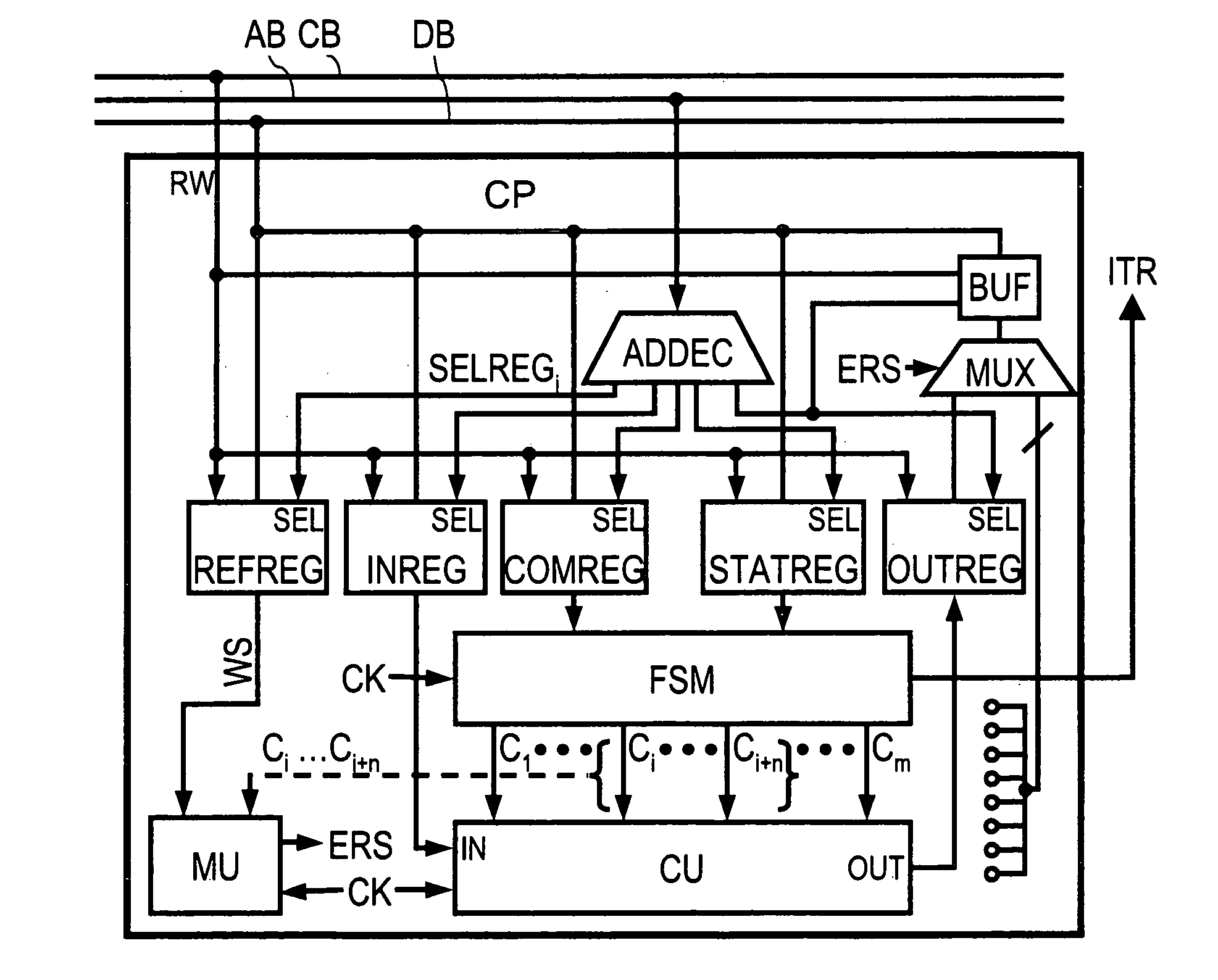
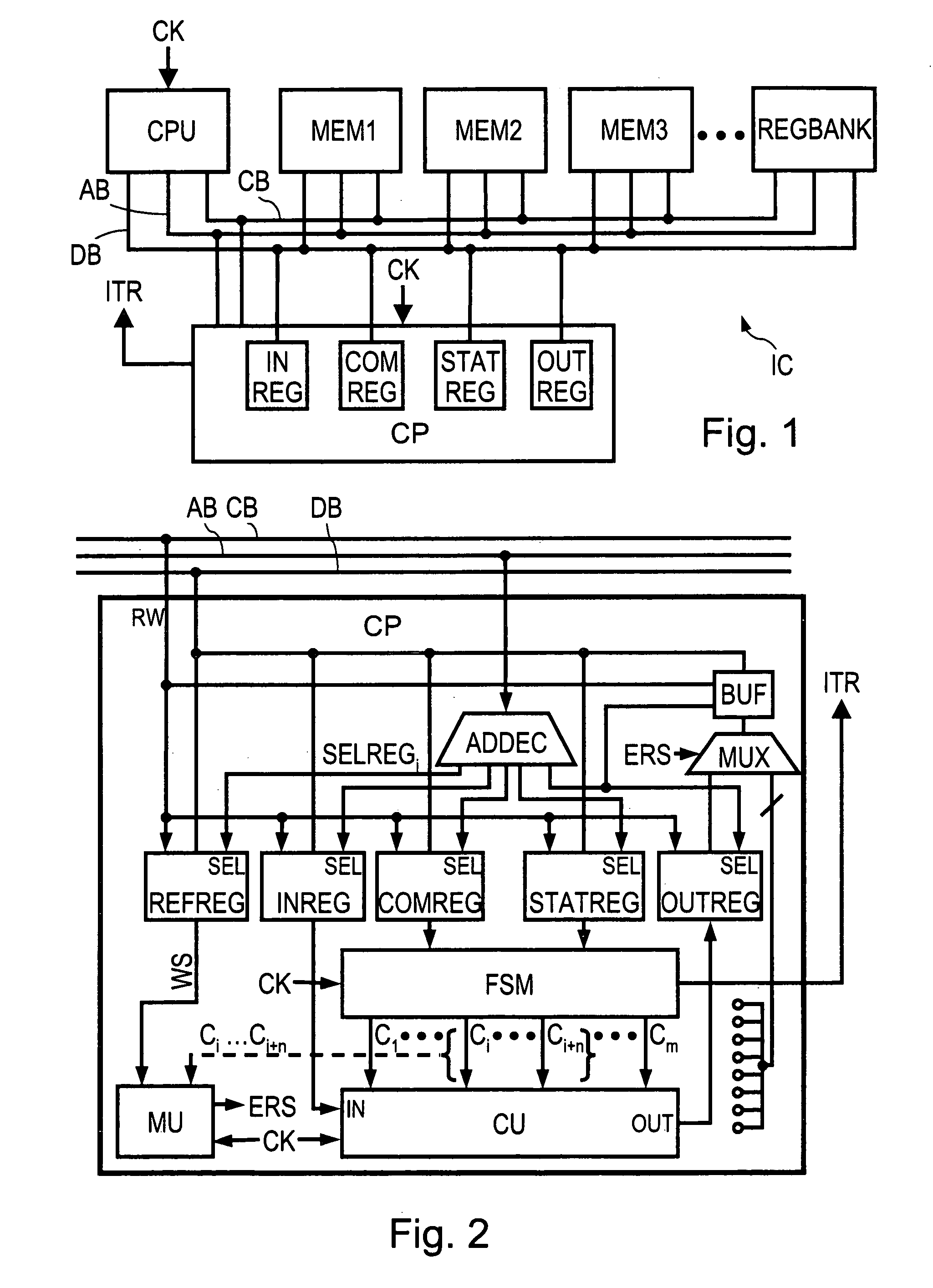
[0013] Another embodiment of the present invention prevents access to certain units of the coprocessor while the error mode is present. An embodiment of the present invention is indeed based on the observation that a voluntary fault injection is generally accompanied by access to “sensitive” units of the coprocessor, such as an output register for example, which enables the fraudor to observe the effects of the fault injection and to deduce information about the coprocessor or secret data it uses therefrom.
[0014] Thus, blocking access to “sensitive” units of the coprocessor, combined with the fact of putting it into an error mode by default which can only be lifted if the command has been correctly executed, provides a high level of security.

Problems solved by technology

However, one type of attack against which a microprocessor integrated circuit must be protected is the injection of errors into the data supplied to a peripheral element, particularly a cryptographic coprocessor (which is generally integrated onto the same silicon chip as the microprocessor).
Now, the monitoring of a derailment during the execution of a program by a microprocessor does not enable an attack on the related coprocessor to be detected, due to the fact that the latter processes each command sent by the microprocessor without interacting with the microprocessor before the end of the processing.
This technique multiplies the calculation times by the number of iterations, which is a major disadvantage.
Further, if an error is highlighted in connection with the state of a state machine, the injection of a fault can result in skipping a state, and thus in masking the error.

Method used


Image

  • Secured coprocessor comprising means for preventing access to a unit of the coprocessor
  • Secured coprocessor comprising means for preventing access to a unit of the coprocessor
  • Secured coprocessor comprising means for preventing access to a unit of the coprocessor

Examples


Embodiment Construction

[0044] In the following description, numerous specific details are given to provide a thorough understanding of embodiments. One skilled in the relevant art will recognize, however, that the invention can be practiced without one or more of the specific details, or with other methods, components, materials, etc. In other instances, well-known structures, materials,,or operations are not shown or described in detail to avoid obscuring aspects of the invention.

[0045] Reference throughout this specification to “one embodiment” or “an embodiment” means that a particular feature, structure, or characteristic described in connection with the embodiment is included in at least one embodiment. Thus, the appearances of the phrases “in one embodiment” or “in an embodiment” in various places throughout this specification are not necessarily all referring to the same embodiment. Furthermore, the particular features, structures, or characteristics may be combined in any suitable manner in one o...


PUM


Abstract

The present invention relates to a coprocessor comprising a calculation unit for executing a command, and a securisation device for monitoring the execution of the command and supplying an error signal having an active value as soon as the execution of the command begins and an inactive value at the end of the execution of the command, if no abnormal progress in the execution of the command has been detected. The coprocessor further comprises means for preventing access to at least one unit of the coprocessor, while the error signal is on the active value. Application is provided particularly but not exclusively to the protection of integrated circuits for smart cards against attacks by fault injection.

Description

TECHNICAL FIELD [0001] The present disclosure generally relates to the protection of integrated circuits, such as integrated circuits for smart cards, against attacks by error injection. [0002] The present disclosure relates more particularly but not exclusively to a method for monitoring the execution by a coprocessor of commands sent in particular by a microprocessor, as well as an integrated circuit comprising a coprocessor comprising means for monitoring the execution of commands. BACKGROUND INFORMATION [0003] A coprocessor is a specific component designed to perform calculations particularly to offload the microprocessor to which it is coupled. It is generally driven by the microprocessor which communicates with it through registers to load calculation data, to configure it and finally to retrieve the results of the calculations and to be informed of the end of the calculations. A coprocessor generally comprises a control block comprising an interface with the data bus of the m...

Claims


Application Information

Patent Timeline
Patent Type & Authority Applications(United States)
IPC IPC(8): G06F15/00
CPCG06F11/28
Inventor BANCEL, FREDERICBERARD, NICOLAS
Owner STMICROELECTRONICS SRL
Why Eureka
Try Eureka