Ejector and ejector cycle device

a cycle device and ejector technology, applied in the direction of machines/engines, machine operation modes, lighting and heating apparatus, etc., can solve the problems of increasing cost, reducing the amount of refrigerant flowing through the evaporator, and degrading the performance of the evaporator, so as to achieve the effect of simple structure of the ejector cycle devi

Inactive Publication Date: 2006-11-30
DENSO CORP
View PDF10 Cites 71 Cited by
  • Summary
  • Abstract
  • Description
  • Claims
  • Application Information

AI Technical Summary

Benefits of technology

[0032] According to a further another object of the present invention, an ejector cycle device includes: an ejector that includes a nozzle portion which reduces pressure of refrigerant to thereby expand the refrigerant, and draws refrigerant by high-velocity refrigerant jetted from the nozzle portion; an evaporator that evaporates refrigerant branched on an upstream sid...

Problems solved by technology

However, one of problems of the vapor compression type refrigerating cycle using the above-mentioned conventional ejector is that when the performance of an ejector is degraded, in particular, in the case of low outside air temperature, the amount of refrigerant flowing...

Method used


Image

  • Ejector and ejector cycle device
  • Ejector and ejector cycle device
  • Ejector and ejector cycle device

Examples


1st embodiment

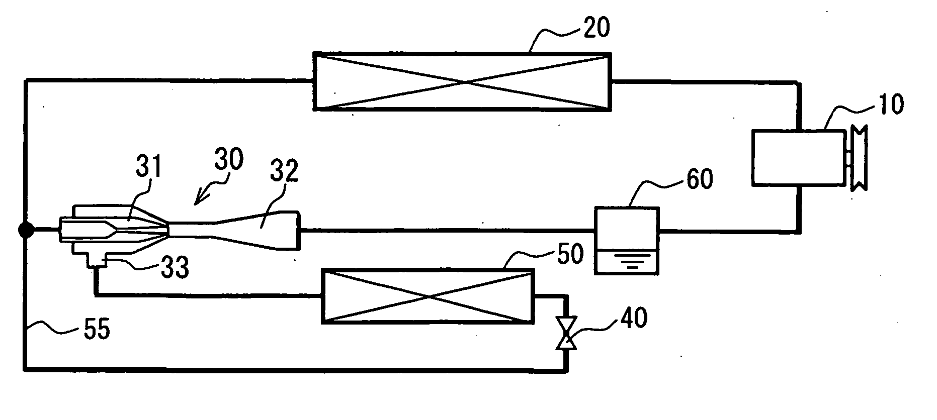
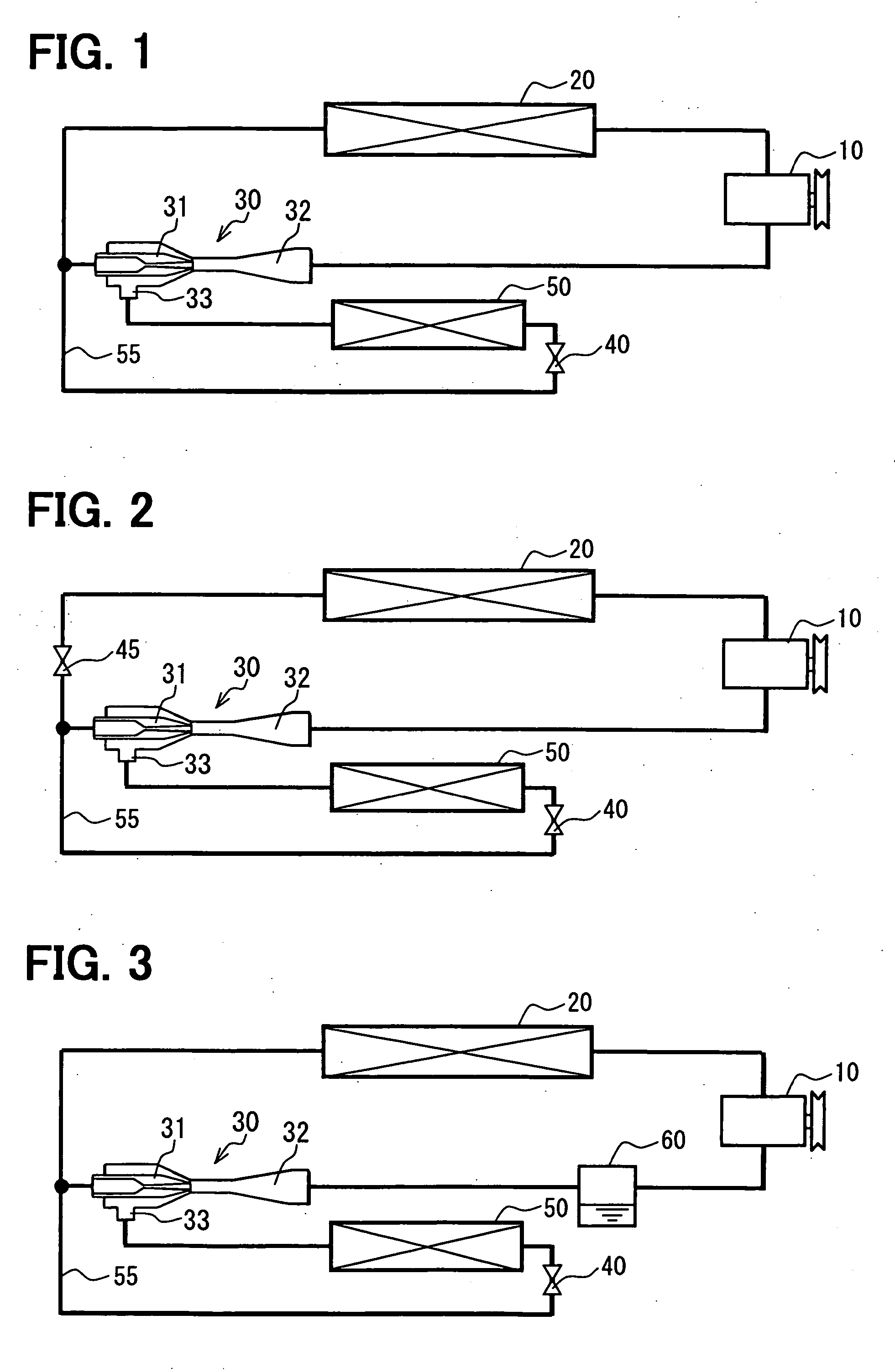
[0062] Hereinafter, the 1st embodiment of the present invention will be described in detail by the use of FIG. 1. FIG. 1 is a schematic diagram of a vapor compression type refrigerating cycle (ejector cycle device) using an ejector in accordance with the 1st embodiment of the present invention. In this embodiment, the vapor compression type refrigerating cycle using an ejector in accordance with the present invention is typically used for such an air conditioner for a vehicle that uses carbon dioxide (CO2) as refrigerant.

[0063] A compressor 10 is supplied with a driving force from a driving source such as a driving engine (not shown) and draws and compresses refrigerant. As the compressor 10 in this embodiment is employed a variable displacement compressor that variably controls the flow rate of discharge refrigerant (discharge refrigerant rate) in such a way that the temperature of refrigerant drawn by the compressor 10 becomes a specified temperature. The flow rate of discharge r...

2nd embodiment

[0076]FIG. 2 is a schematic diagram of a vapor compression type refrigerating cycle (ejector cycle device) using an ejector in accordance with the 2nd embodiment of the present invention. Features in which the 2nd embodiment is different from the 1st embodiment will be mainly described. In this embodiment, a flow control valve 45 as flow controlling means for controlling the flow rate of refrigerant is arranged in a refrigerant circulating passage between the radiator 20, and the nozzle portion 31 and the branch passage 55.

[0077] In the basic cycle construction of the 1st embodiment, even when a variable flow type ejector is used as the ejector 30 so as to control the flow rate of refrigerant, when the flow rate of the driving flow is decreased, the flow rate of the suction flow is increased so that the total flow rate of refrigerant flowing through the compressor 10 is not much varied. In this case, the flow rate of refrigerant may be not controlled as much as we expect.

[0078] In...

3rd embodiment

[0079]FIG. 3 is a schematic diagram of a vapor compression type refrigerating cycle using an ejector 30 in accordance with the 3rd embodiment of the present invention. Features in which the 3rd embodiment is different from the above-mentioned respective embodiments will be mainly described. In this embodiment, a vapor / liquid separator 60 that separates circulating refrigerant into vapor-phase refrigerant and liquid-phase refrigerant and supplies only the vapor-phase refrigerant to the compressor 10 and accumulates the liquid-phase refrigerant is located between the outlet of the ejector 30 and the compressor 10.

[0080] The vapor / liquid separator 60 in FIG. 3 is an accumulator into which refrigerant flowing out of the ejector 30 flows and which separates the flowing-in refrigerant into vapor-phase refrigerant and liquid-phase refrigerant and accumulates the liquid-phase refrigerant. The separated vapor-phase refrigerant is drawn by the compressor 10 and the separated liquid-phase ref...


PUM


Abstract

An ejector cycle device includes a compressor that draws and compresses refrigerant, a radiator that radiates heat of high-pressure refrigerant discharged from the compressor, an ejector, a branch passage branched from a refrigerant passage between the radiator and a nozzle portion of the ejector and coupled to a suction port of the ejector, a throttle unit that is arranged in the branch passage and decompresses refrigerant, and an evaporator that is arranged on a downstream side of refrigerant flow of the throttle unit in the branch passage and evaporates refrigerant. Accordingly, even when a suction performance of the ejector is lowered, refrigerant can flow through the evaporator.

Description

CROSS REFERENCE TO RELATED APPLICATION [0001] This application is based on Japanese Patent Applications No. 2005-151590 filed on May 24, 2005, No. 2005-151591 filed on May 24, 2005, No. 2005-195537 filed on Jul. 4, 2005, No. 2005-210151 filed on Jul. 20, 2005, and No. 2005-213273 filed on Jul. 22, 2005, the contents of which are incorporated herein by reference in its entirety. BACKGROUND OF THE INVENTION [0002] 1. Field of the Invention [0003] The present invention relates to an ejector and an ejector cycle device using the same. The ejector cycle device can be suitably used for a vapor compression type refrigerating cycle using an ejector. [0004] 2. Description of the Related Art [0005] As for a vapor compression type refrigerating cycle using an ejector, there is proposed a vapor compression type refrigerating cycle as described, for example, in JP-B1-3322263 (corresponding to U.S. Pat. No. 6,477,857, U.S. Pat. No. 6,574,987) that employs a vapor / liquid separator and an ejector f...

Claims


Application Information

Patent Timeline
IPC IPC(8): F25B19/02F25B1/06
CPCF25B5/04Y02B30/743F25B40/00F25B41/00F25B2341/0012F25B2341/0015F25B2400/23F25B2500/01F25B2600/111F25B2600/112F25B2700/1933F25B2700/197F25B2700/21151F25B2700/2117F25B2700/21175F25B13/00B60H2001/3298F25B1/00F25B43/00
Inventor TAKEUCHI, HIROTSUGUSAITO, MIKAOSHITANI, HIROSHINISHIDA, SHINSUGIURA, TAKAYUKI
Owner DENSO CORP
Why Eureka
Try Eureka