Soldering method, electronic part, and part-exchanging method

a technology of electronic parts and surface temperature distribution, applied in the direction of welding/cutting media/materials, welding apparatus, manufacturing tools, etc., can solve the problems of difficult mounting of electronic parts using pb-free solder, same problem in the exchanging process, and difficult control of heating temperature, so as to facilitate temperature control, prevent defects in electronic parts, and uniform surface temperature distribution of electronic parts

Inactive Publication Date: 2006-11-30
FUJITSU LTD
View PDF7 Cites 5 Cited by
  • Summary
  • Abstract
  • Description
  • Claims
  • Application Information

AI Technical Summary

Benefits of technology

[0029] According to the present invention, it is possible to make the surface temperature distribution of the electronic part uniform when heating, and this facilitates temperature control during the reflow soldering; further, it is possible to prevent defects in the electronic parts due to heating.
[0030] According to a third aspect of the present invention, there is provided a part-exchanging method for exchanging at least one electronic part from a substrate on which a plurality of electronic parts are mounted on a surface of the substrate, comprising the steps of: disposing a heat capacity enhancing member on the electronic parts around the electronic part to be exchanged, said heat capacity enhancing member including a gel-like material able to enhance the heat capacity of the electronic parts; and heating the electronic part to be exchanged and removing said electronic part from the substrate.
[0031] According to the present invention, when heating the electronic part to be exchanged, because a heat capacity enhancing member is disposed on the electronic parts around the electronic part to be exchanged, it is possible to prevent heat damage to these electronic parts when exchanging that electronic part.

Problems solved by technology

For this reason, it is not easy to control the heating temperature during the reflow process, and it is difficult to mount the electronic parts by using the Pb-free solder.
Further, after the electronic parts are mounted, if it is found that an electronic part is faulty, this electronic part is exchanged.
Therefore, the same problem occurs in the exchanging process as in the original mounting process.

Method used


Image

  • Soldering method, electronic part, and part-exchanging method
  • Soldering method, electronic part, and part-exchanging method
  • Soldering method, electronic part, and part-exchanging method

Examples


Embodiment Construction

[0044] Below, preferred embodiments of the present invention will be explained with reference to the accompanying drawings.

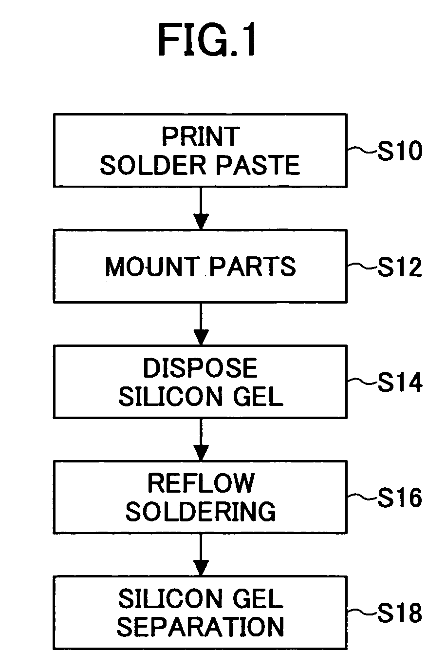
[0045]FIG. 1 is a flowchart illustrating a soldering method according to an embodiment of the present invention.

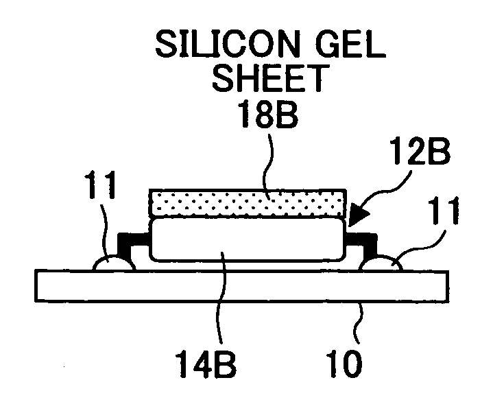
[0046] As illustrated in FIG. 1, the soldering method of the present embodiment includes a step of printing a solder paste on a substrate (S18), a step of mounting an electronic part on the substrate (S12), a step of disposing a silicon gel on the electronic part (S14), a step of reflow soldering (S16), and a step of silicon gel separation (S18).

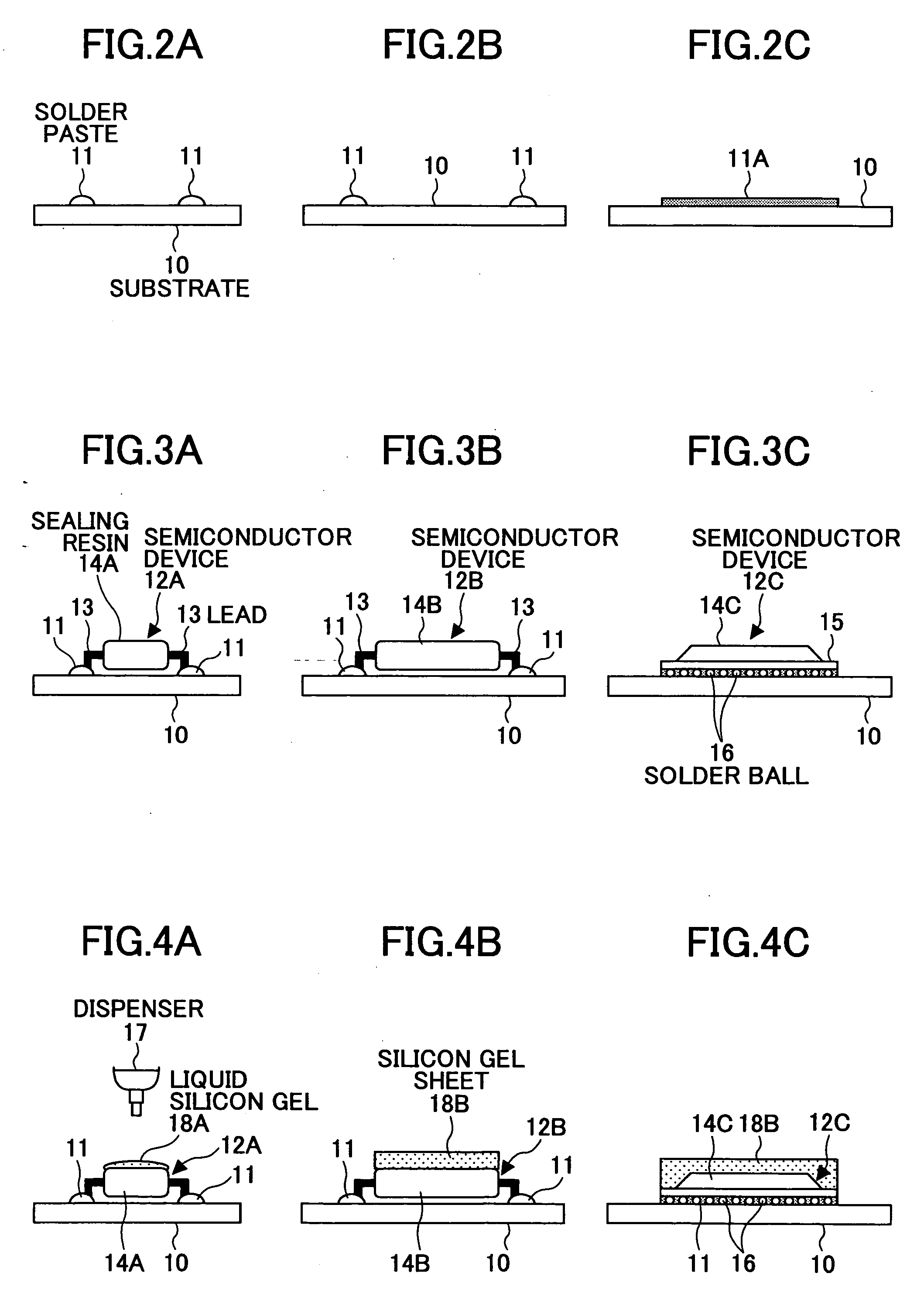
[0047] Below, the soldering method shown in FIG. 1 is explained with reference to FIG. 2 through FIG. 6 .

[0048] Note that in FIG. 2A, FIG. 3A, FIG. 4A, FIG. 5A, and FIG. 6A, a QFP-type semiconductor device is used as an example of the electronic part, and a liquid silicon gel 18A is used as an example of a silicon gel 18; in FIG. 2B, FIG. 3B, FIG. 4B, FIG. 5B, and FIG. 6B, a QFP-type semiconductor device is...


PUM

PropertyMeasurementUnit
heat resistance temperatureaaaaaaaaaa
surface temperatureaaaaaaaaaa

Abstract

A soldering method for soldering an electronic part on a substrate by reflow soldering is disclosed that includes the steps of applying a solder paste on the substrate; mounting the electronic part on the substrate by using the solder paste; disposing a heat capacity enhancing member on the electronic part, the heat capacity enhancing member including a gel-like material able to enhance the heat capacity of the electronic part; and soldering the electronic part onto the substrate by reflow soldering with the heat capacity enhancing member being applied thereon.

Description

CROSS-REFERENCE TO RELATED APPLICATION [0001] This patent application is based on Japanese Priority Patent Application No. 2005-159837 filed on May 31, 2005, the entire contents of which are hereby incorporated by reference. BACKGROUND OF THE INVENTION [0002] 1. Field of the Invention [0003] The present invention relates to a soldering method, an electronic part, and a part-exchanging method, and particularly, to a soldering method, an electronic part, and a part-exchanging method suitable for soldering by using a Pb-free solder. [0004] 2. Description of the Related Art [0005] In recent and continuing years, along with further progress in compactness and high performance of electronic devices, significant technical progress has been made in compactness of electronic parts installed in the electronic device, an installation device for installing the electronic parts on a substrate, and an installation method. Especially, as a technique of installing the electronic part on the substra...

Claims


Application Information

Patent Timeline
Patent Type & Authority Applications(United States)
IPC IPC(8): B23K1/20B23K5/00B23K35/38
CPCH01L24/98H01L2924/014H01L2924/01082H05K1/0201H05K3/284H05K3/288H05K3/3494H05K2201/062H05K2203/0126H05K2203/176H05K2203/304H01L2924/01005H01L2924/01006H01L2924/01322H01L2924/01033
Inventor YAMAMOTO, TSUYOSHIHIRUMA, AKIOMIKOYAMA, FUMIGI
Owner FUJITSU LTD
Why Eureka
Try Eureka