Electro-optical scanner having exit window with light collecting optics

Active Publication Date: 2006-11-30
SYMBOL TECH LLC
View PDF2 Cites 9 Cited by
  • Summary
  • Abstract
  • Description
  • Claims
  • Application Information

AI Technical Summary

Benefits of technology

[0014] Having the focal point of the light collection lens lie in the plane of the scanning beam substantially eliminates the parallax effect. Thus, the light collection lens does not require an additional field of view in a direction orthogonal to the scanning beam axis. Moreover, since the light coll

Problems solved by technology

One problem with the collection lens 260 of a non retro-reflective scanner stems from parallax effect.
Unfortunately, an unfortunate result of increasing the vertical field of vision of the light collection lens 260 more ambien

Method used


Image

  • Electro-optical scanner having exit window with light collecting optics
  • Electro-optical scanner having exit window with light collecting optics
  • Electro-optical scanner having exit window with light collecting optics

Examples


Embodiment Construction

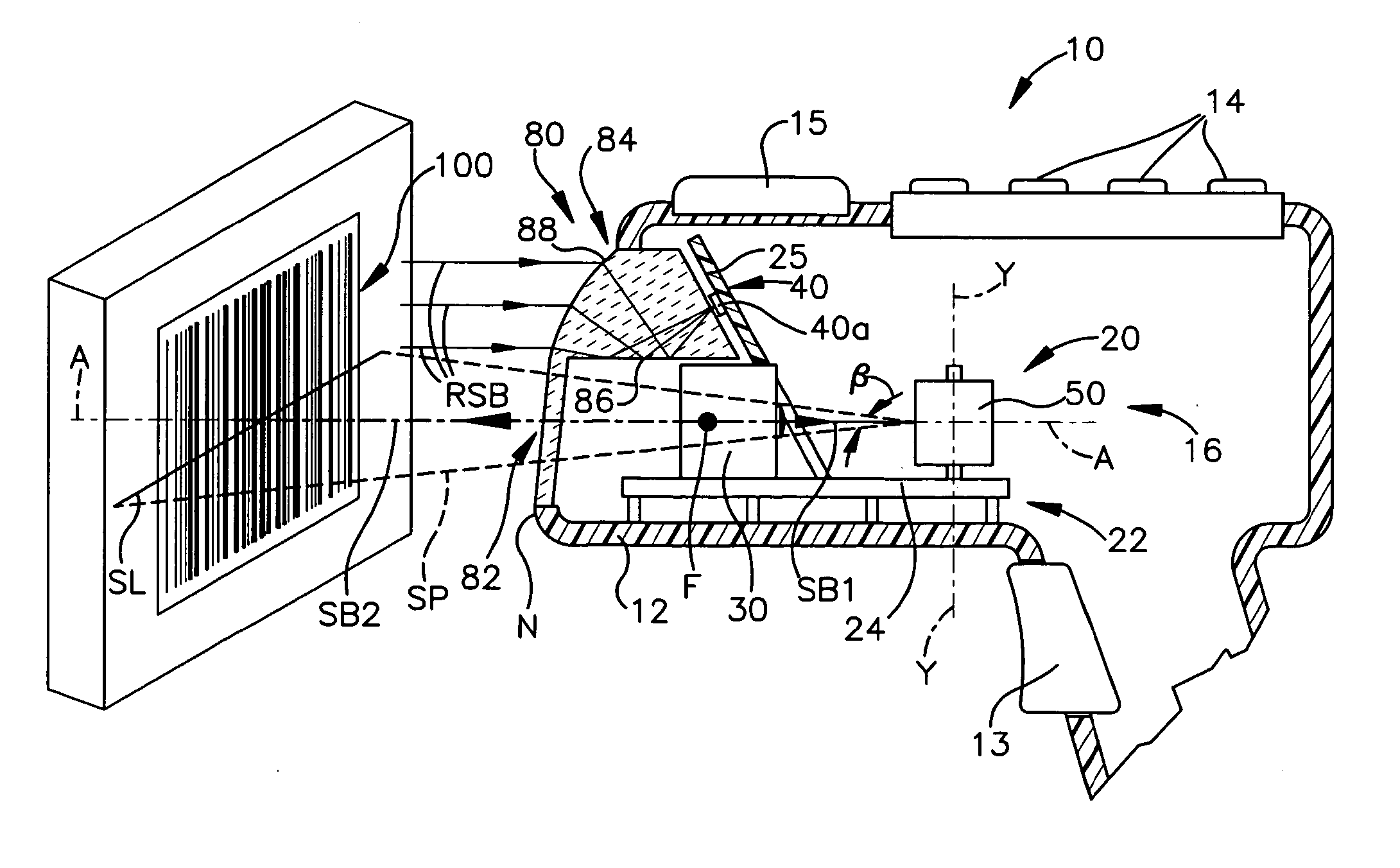
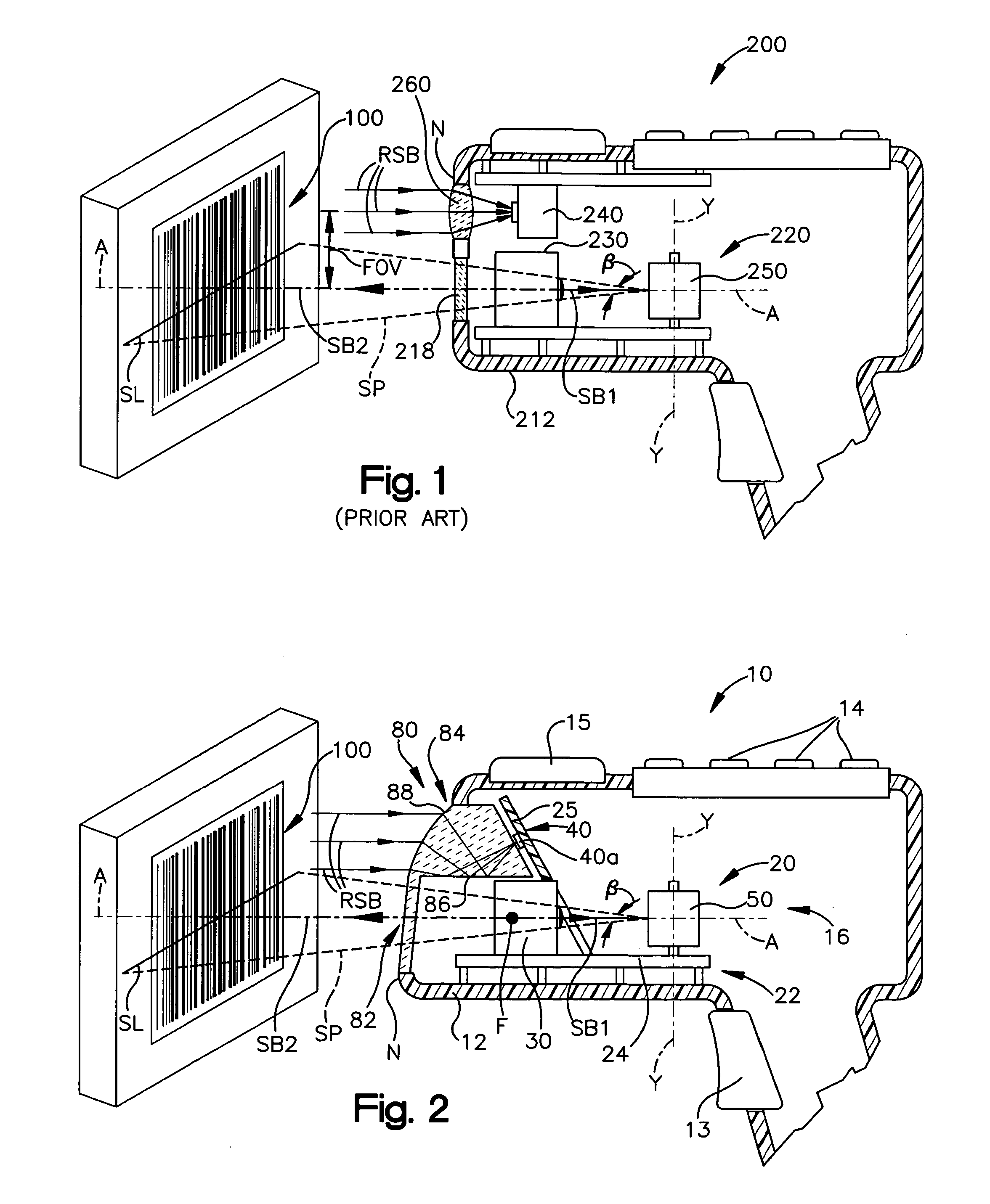
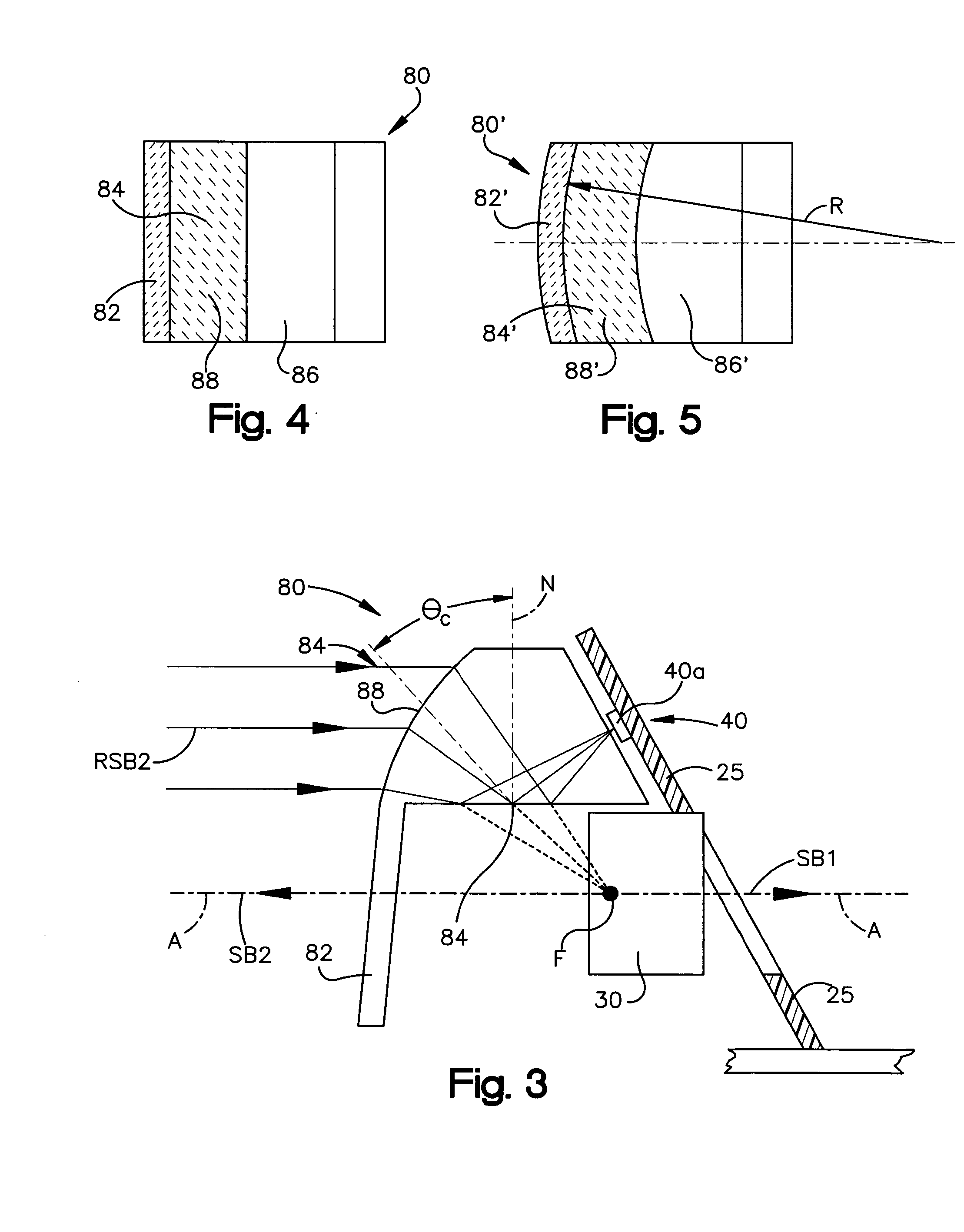
[0028] A portable electro-optical scanner of the present invention is shown schematically at 10 in FIG. 2. The scanner 10 may be used to scan and decode bar codes, such as, 1D and 2D bar codes and postal codes. As used herein, the term “bar code” is intended to be broadly construed to cover not only bar code symbol patterns comprised of alternating bars and spaces, but also other graphic patterns, such as dot or matrix array patterns and, more generally, indicia having portions of different light reflectivity or surface characteristics that result in contrasting detected signal characteristics that can be used for encoding information and can be scanned and decoded with the scanner 10. FIGS. 1 and 3 depict a target 1D bar code 100 affixed to a product 102.

[0029] In one preferred embodiment of the present invention, the scanner 10 is a hand held, portable bar code reader. The scanner 10 is supported in a housing 12 that can be carried and used by a user walking or riding through a s...


PUM


Abstract

A portable electo-optical scanner for reading a target bar code having a plurality of bar code elements. The portable scanner includes: a housing supporting a scanning module and an optic system. The scanning module electro-optically scans the target bar code with a scanning beam and collects reflected light returning from the bar code. The scanning module includes a beam source emitting a scanning beam, beam directing apparatus causing the scanning beam to be repetitively scanned along a scanning plane intersecting the target bar code and photodetector circuitry receiving light from the target bar code. The optic system includes an exit window, a light collection lens and a reflective surface. The scanning beam passes through the exit window upon exiting the housing. The light collection lens receives reflected light from the target bar code and directing the reflected light toward a focal point. The focal point lying on the scanning plane of the scanning beam. The reflective surface is disposed between the light collection lens and the focal point to redirect the reflected light passing through the light collection lens toward the photodetector circuitry.

Description

FIELD OF THE INVENTION [0001] The present invention relates to an electro-optical scanner for reading bar codes and, more particularly, to a non retro-reflective scanner including an exit window having a light collecting system incorporating a total internal reflection surface. BACKGROUND OF THE INVENTION [0002] Electro-optical scanners are widely used for reading bar codes, including one dimensional and two dimensional bar codes. A scanner typically includes a scanning module which: generates a scanning beam; repetitively directs and scans the beam across a target object, such as a bar code; receives reflected light from the target object; and digitizes and decodes the reflected light to decode the information encoded in the bar code. The scanning module is supported in a housing of the hand held portable scanner which also supports a power supply and other electronics of the scanner. [0003] The scanning module scanning beam (typically a laser beam emitted by a laser diode) is dire...

Claims


Application Information

Patent Timeline
IPC IPC(8): G06K7/10
CPCG06K7/10702G06K7/10554
Inventor VINOGRADOV, IGOR R.SHI, TSI DAVID
Owner SYMBOL TECH LLC
Why Eureka
Try Eureka