High fidelity electrically calibrated pyroelectric radiometer

a radiometer and high-fidelity technology, applied in the field of radiometry, can solve problems such as rapid measurements

Inactive Publication Date: 2006-11-30
PHELAN JR ROBERT JOSEPH
View PDF9 Cites 18 Cited by
  • Summary
  • Abstract
  • Description
  • Claims
  • Application Information

AI Technical Summary

Problems solved by technology

Some make rapid measurements and some are very slow.

Method used


Image

  • High fidelity electrically calibrated pyroelectric radiometer
  • High fidelity electrically calibrated pyroelectric radiometer
  • High fidelity electrically calibrated pyroelectric radiometer

Examples


Embodiment Construction

—BASIC OPERATION

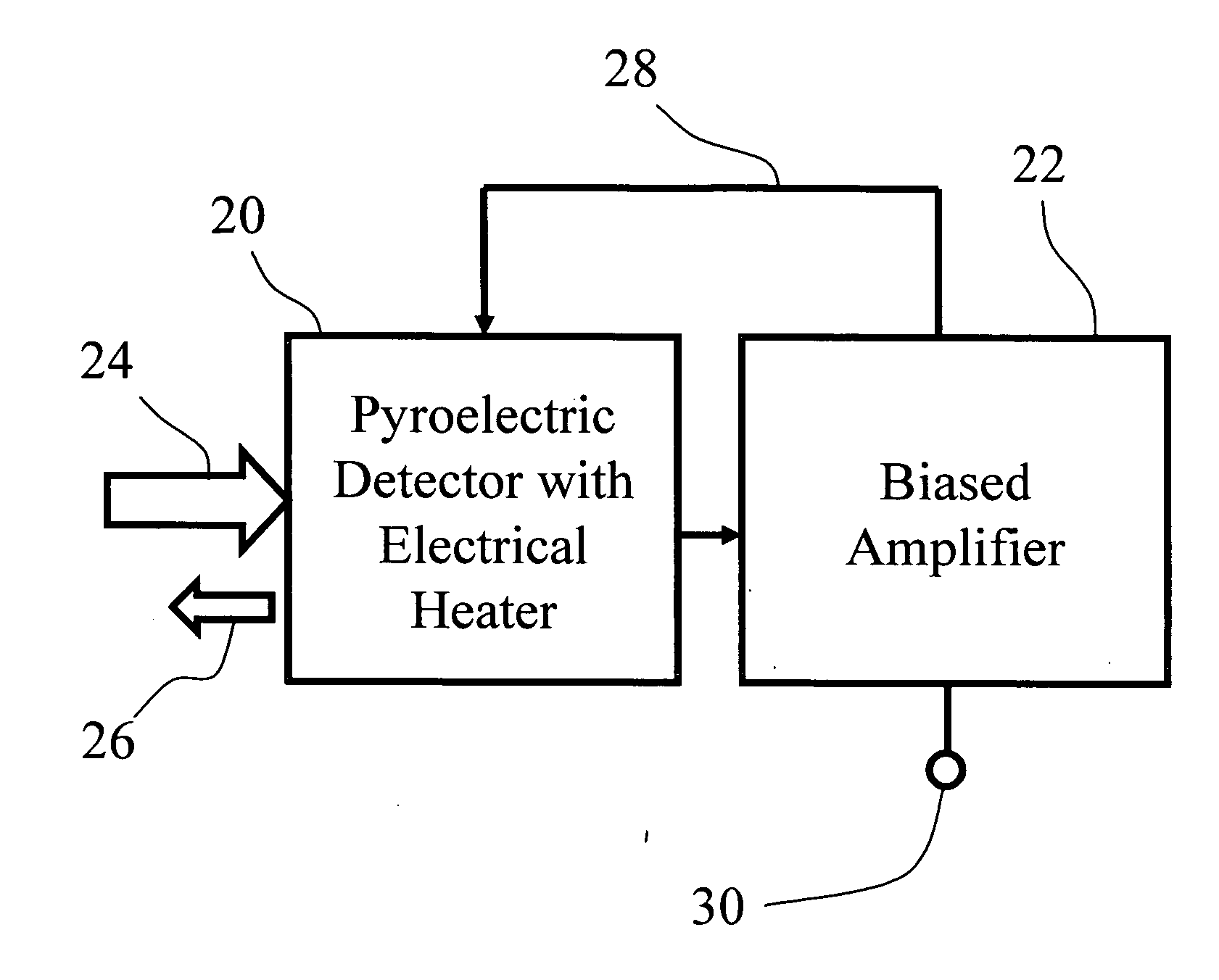
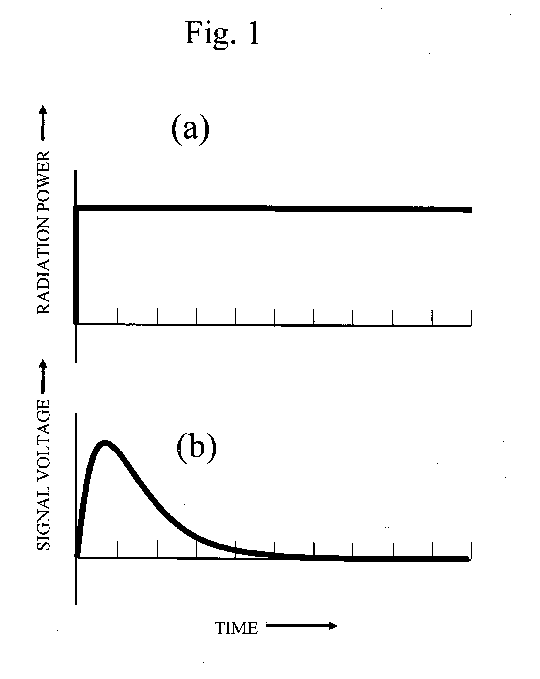
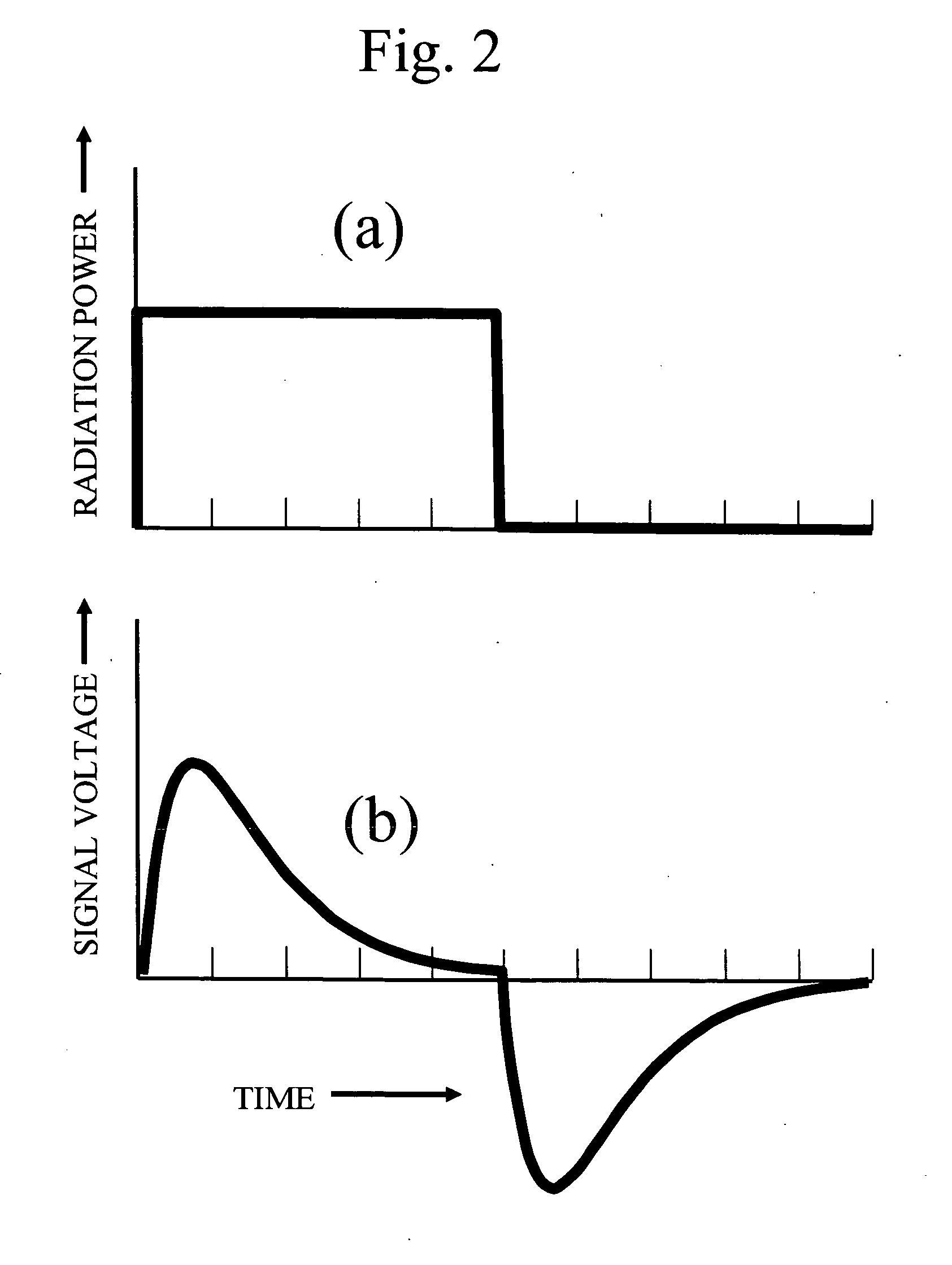
[0034] For the present embodiment of an electrically calibrated pyroelectric radiometer, the waveform for the electrical calibration power is derived directly from the pyroelectric detector signal generated by the incident radiation waveform. This mode of operation leads to improved signal fidelity, and an accurate electrical calibration. This mode of operation is substantially different than previous electrically calibrated pyroelectrics which used a signal generated and conditioned from a separate detector to provide the electrical power.

[0035] To obtain an improved signal, a biased, electrical power feedback circuit is used. A bias electrical power is applied to a detector heater, and this elevates the pyroelectric temperature above a reference temperature. The reference temperature is the temperature of a heat-sink structure to which the pyroelectric is in thermal contact. When a radiation signal is incident on the detector, the detector temperature rises, and t...


PUM


Abstract

Using biased, electrical power feedback to an electrical heater, the output signal from a pyroelectric detector is made to follow the waveform of incident electromagnetic radiation. The feedback power is applied to the detector to reduce the rate of change of the detector temperature that would otherwise be caused by the absorbed radiation. The combined signals from the radiation and feedback power produce a response that follows the radiation waveform with a fast rise time and with substantially less droop than previously reported. The high fidelity of the response waveform allows for a substantial simplification of the optical chopper designs and electronics needed to implement electrical calibration. In contrast to previous electrical calibration with pyroelectrics that needed very specialized electronics, with this method a variety instruments can be used for reading pyroelectric signals. The method allows for signal processing that reduces phase noise and yields very accurate radiation power measurements.

Description

CROSS-REFERENCE TO RELATED APPLICATIONS [0001] Not Applicable FEDERALLY SPONSORED RESEARCH [0002] Not Applicable SEQUENCE LISTING OR PROGRAM [0003] Not Applicable BACKGROUND OF THE INVENTION—FIELD OF THE INVENTION [0004] This invention relates to the field of radiometry. Specifically, to accurate power measurements of electromagnetic radiation over a wide range of wavelengths from the ultraviolet, through the visible, the infrared, T-rays, microwaves, and beyond to radio waves. This invention uses pyroelectric detectors to measure this wide range of radiation wavelengths. BACKGROUND OF THE INVENTION—THE PYROELECTRIC DETECTOR RESPONSE [0005] The pyroelectric detector is classified as a thermal detector. Electromagnetic radiation incident on the detector is absorbed. The absorbed radiation heats the detector, and a signal current is generated that is proportional to the time rate of change of the temperature of the pyroelectric. No other source of power is required to produce a signal...

Claims


Application Information

Patent Timeline
Patent Type & Authority Applications(United States)
IPC IPC(8): G01J5/00
CPCG01J5/061G01J5/62G01J5/34G01J5/0805
Inventor PHELAN, ROBERT JOSEPH JR.
Owner PHELAN JR ROBERT JOSEPH
Why Eureka
Try Eureka