Support member of vibrator

a technology of supporting member and vibrator, which is applied in the direction of generator/motor, turn-sensitive devices, instruments, etc., can solve the problem of difficult control of drift, and achieve the effect of reducing the zero point temperature drift of detection signals described abov

Active Publication Date: 2006-11-30
SEIKO EPSON CORP
View PDF3 Cites 3 Cited by
  • Summary
  • Abstract
  • Description
  • Claims
  • Application Information

AI Technical Summary

Benefits of technology

[0004] An object of the present invention is to provide a structure for supporting a vibrator capable of reducing a zero point temperature drift of a detection signal in a system for measuring a physical quantity using a vibrator.
[0011] According to the supporting member and supporting structure of the present invention, the zero point temperature drift of detection signal described above can be reduced. The present invention will be described further in detail, referring to the attached drawings.

Problems solved by technology

Such temperature range where the temperature drift is observed may be variously shifted such as in a range of minus 40 to plus 20° C. in one vibrator and in a range of minus 40 to plus 60° C. in another vibrator, so that the drift is difficult to control.

Method used


Image

  • Support member of vibrator
  • Support member of vibrator
  • Support member of vibrator

Examples


example a

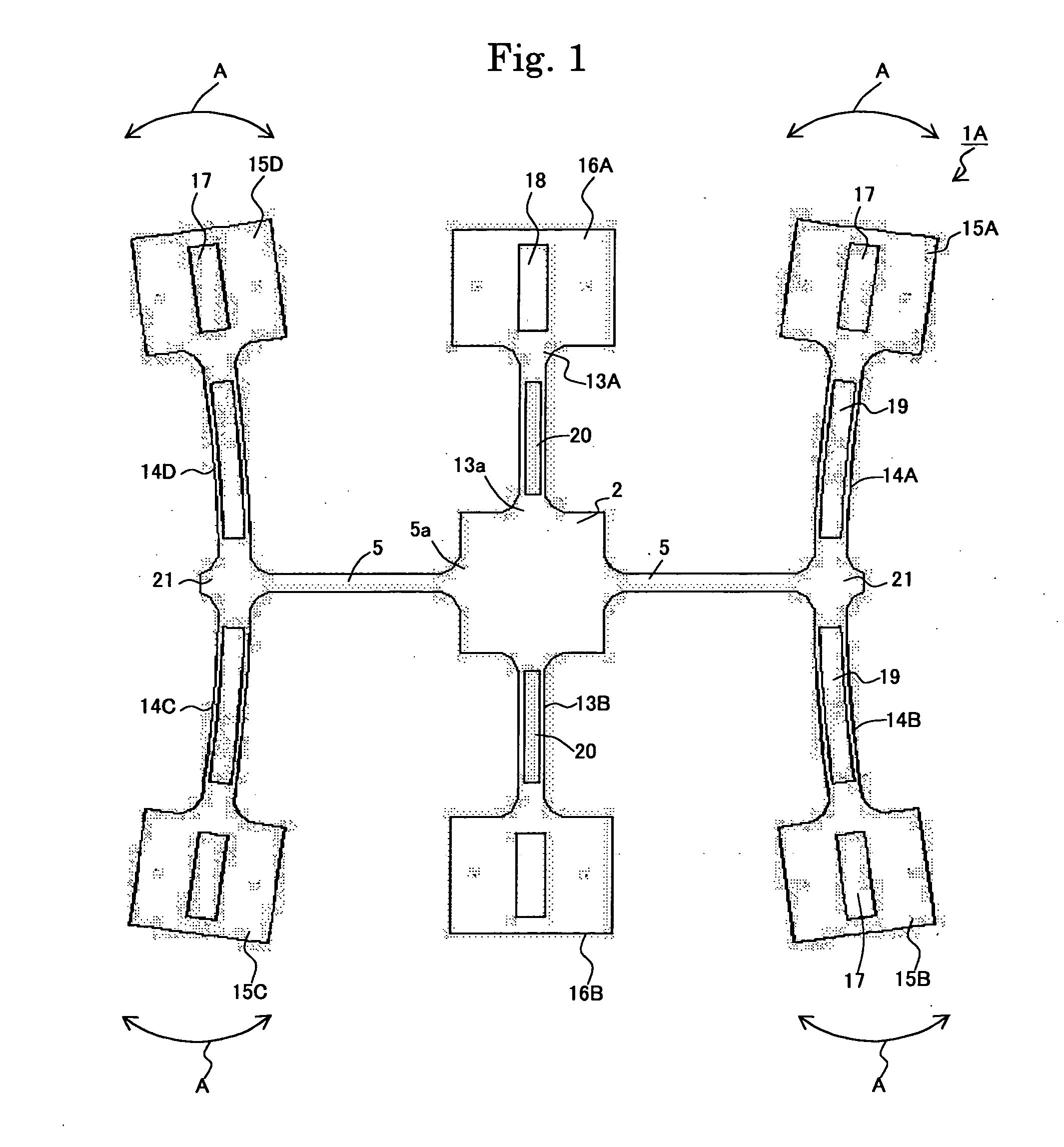
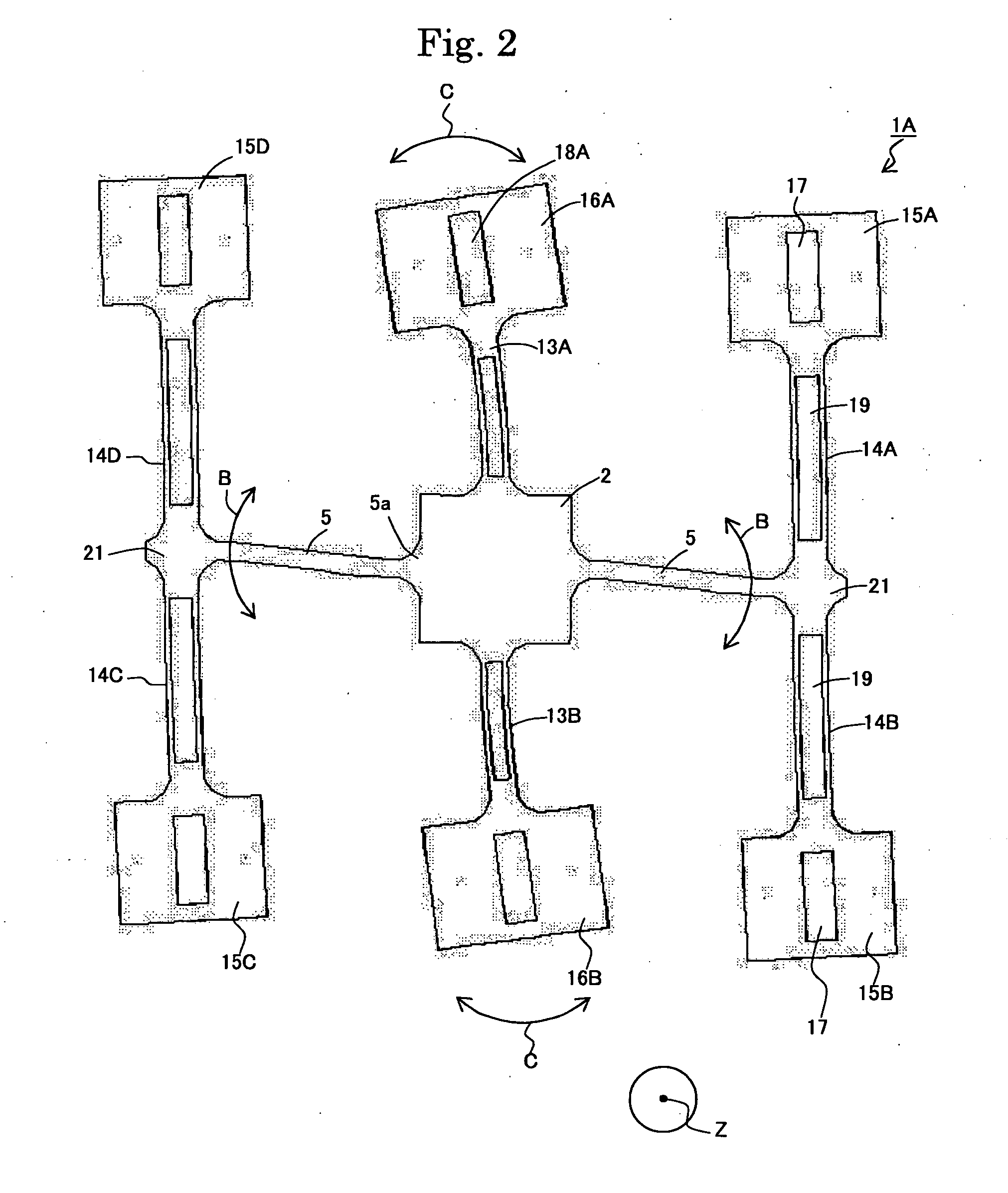
[0071] The vibrator and the supporting structure shown in FIGS. 15 and 16 were produced. According to the present example, however, each of the constituent parts was changed as shown in each of FIGS. 17 to 21.

[0072] Specifically, the vibrator 1A shown in FIGS. 1 and 2 was used. A chromium film of 100 angstroms in thickness and a gold film of 1500 angstroms in thickness were formed in predetermined regions on a wafer made of a Z-plate of quartz with a thickness of 0.1 mm, by sputtering. Both main faces of the wafer were coated with resist films.

[0073] The wafer was then immersed in aqueous solution of iodine and potassium iodide to remove excessive gold in the gold film by etching, and was further immersed in aqueous solution of cerium-ammonium nitrate and perchloric acid to remove excessive chromium in the chromium film by etching. The wafer was etched by immersing the wafer in ammonium bifluoride at a temperature of 80° C. for 20 hours to form the external shape of the vibrator 1...

experiment b

(Experiment B)

[0078] The vibrator 1A was produced according to the same procedure as the Experiment A. The vibrator was supported on the supporting system having a shape shown in FIG. 23 and mount in a package. The plate shaped bodies 23, 24 and substrate 32 were same as those described in the Experiment A. The height of the vibrator 1A with respect to the surface of the supporting plate was made 0.1 mm. The contact pad, material, dimensions and fixing method of the bonding wire were same as the Experiment A, except that L3 and L4 in FIG. 23 were changed as shown in table 2. Further, the radius of curvature of the curved portion 32a in experiment number 5 was 0.08 mm, and the radius of curvature of the curved portion 32a in the experiment number 6 was 9.3 mm.

[0079] The thus obtained vibratory gyroscope was measured for each resonance frequency of each vibration mode using an impedance analyzer, according to the same procedure as the Experiment A. The results were shown in table 2. ...


PUM


Abstract

The present invention provides, in a physical quantity measuring system using a vibrator, a supporting structure of a vibrator for reducing the zero-point temperature drift of detection signal. It is provided a supporting member 22 for supporting a vibrator 1A with bonding wires 26. The supporting member 22 has a supporting plate 40 with an opening 25 formed therein to be positioned direct under a vibrator 1A, and a bonding wire 26 comprising a bonding end 29 to be bonded with the vibrator 1A, a fixed portion 26a fixed on the supporting plate 40 and a bent portion 28 direct under the opening 25. A distance “L1” between the bent portion 28 and a position 39 where the bonding wire 26 starts to protrude from the supporting plate 40 is 10 percent or more of a distance “L2” of the bent portion 28 and the bonding end 29.

Description

FIELD OF THE INVENTION [0001] The present invention relates to a member and structure for supporting a vibrator suitable for a vibratory gyroscope. BACJGROUND OF THE INVENTION [0002] According to a vehicle control system, a vibratory gyroscope and its vibrator is subjected to a wide temperature range including high and low ambient temperatures. Such temperature range normally includes minus 40° C. to plus 85° C. and may be more wider in a more severe specification. Particularly when a vibrator is made of a piezoelectric single crystal, the temperature dependency of the single crystal may affect the stability of the gyroscope. The assignee filed a Japanese patent publication 2001-12955A and disclosed a vibratory gyroscope having a specific shape with low noise level. Further, in Japanese patent publication No. 2001-82962A, it is disclosed that a vibrator is adhered to a supporting member with an adhesive having a tan δ of not higher than 0.1 within the temperature range for use, for ...

Claims


Application Information

Patent Timeline
Patent Type & Authority Applications(United States)
IPC IPC(8): H01L41/00G01C19/56G01C19/5628
CPCG01C19/5621G01C19/5783G01C19/5628
Inventor ISHIKAWA, SEIJIKIKUCHI, TAKAYUKIHAYASHI, SHIGEKI
Owner SEIKO EPSON CORP
Why Eureka
Try Eureka