Coil component and electronic device

a technology of coil components and electronic devices, which is applied in the direction of transformers/inductance coils/windings/connections, printed circuit aspects, etc., can solve the problems of dropping the reliability of the device, and achieve the effect of preventing short circuiting, increasing the mounting strength of the coil component on the circuit board, and reducing the influence of high temperature heat on other components on the circuit board

Active Publication Date: 2006-11-30
TDK CORPARATION
View PDF8 Cites 64 Cited by
  • Summary
  • Abstract
  • Description
  • Claims
  • Application Information

AI Technical Summary

Benefits of technology

[0021] When this electrode device is fabricated, the coil component is mounted on the circuit board in a state where conductive paste is intervened between an area from the terminal electrodes placed in the mounting portion of the core element to a base exposed area of the mounting portion, and the electrode patterns on the circuit board. By applying the conductive paste not only to the terminal electrodes but also to the base exposed area of the mounting portion which has good contact (adhesion), the mounting strength of the coil component on the circuit board can be increased. By mounting the coil component on the circuit board using conductive paste, mounting at sufficiently low temperature than the case of mounting by solder becomes possible, so the influence of high temperature heat on other components on the circuit board can be decreased. At this time, intervening the conductive paste between the base exposed area of the mounting portion and the electrode patterns tends to cause ion migration if voltage is applied to each terminal metal fitting in a state where moisture is caught between the core element and circuit board. If ion migration occurs, metal (e.g. silver) dendrites may be generated in the conductive paste between adjacent electrode patterns, as mentioned above. However in the area between each terminal electrode in the mounting portion, the hollow portion, opening to the mounting side face of the mounting portion, is formed, so the progress of forming the dendrites is suppressed by the hollow portion. This can prevent short circuiting between each terminal electrode caused by ion migration. Therefore the coil component can be mounted on the circuit board by the conductive paste without problems.
[0022] According to the present invention, when the coil component is mounted on the circuit board by conductive paste, the generation of short circuiting between the terminal electrodes due to ion migration can be prevented, so no problems occur even if the coil component is mounted on the circuit board using conductive paste. Therefore the coil component need not be mounted on the circuit by high temperature soldering, so the influence on other components on the circuit board can be decreased. Also the conductive paste is applied to the terminal electrodes and mounting portion, so the mounting strength of the coil component on the circuit board can be increased. As a result, the reliability of the electronic device can be improved.

Problems solved by technology

However in the case of mounting by soldering, high temperature heat may affect other components, which drops the reliability of the device.

Method used


Image

  • Coil component and electronic device
  • Coil component and electronic device
  • Coil component and electronic device

Examples


first embodiment

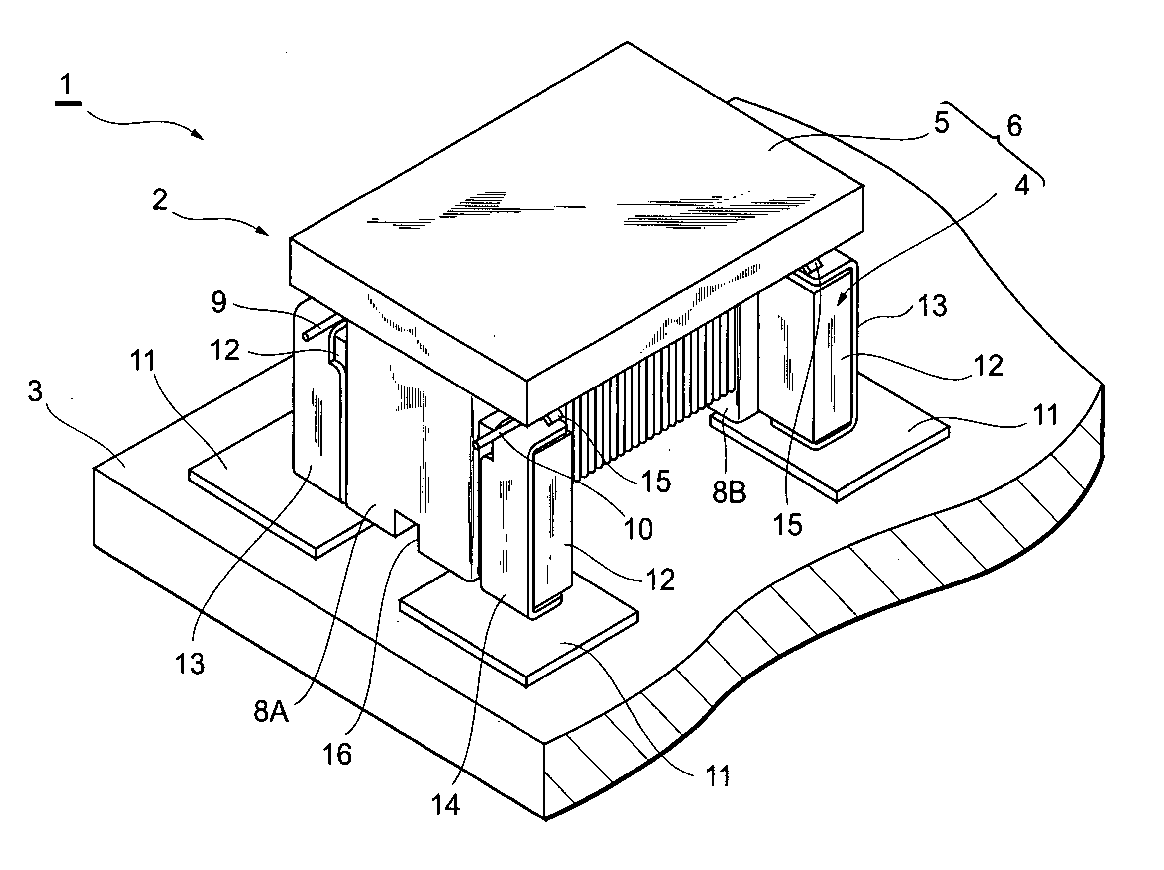
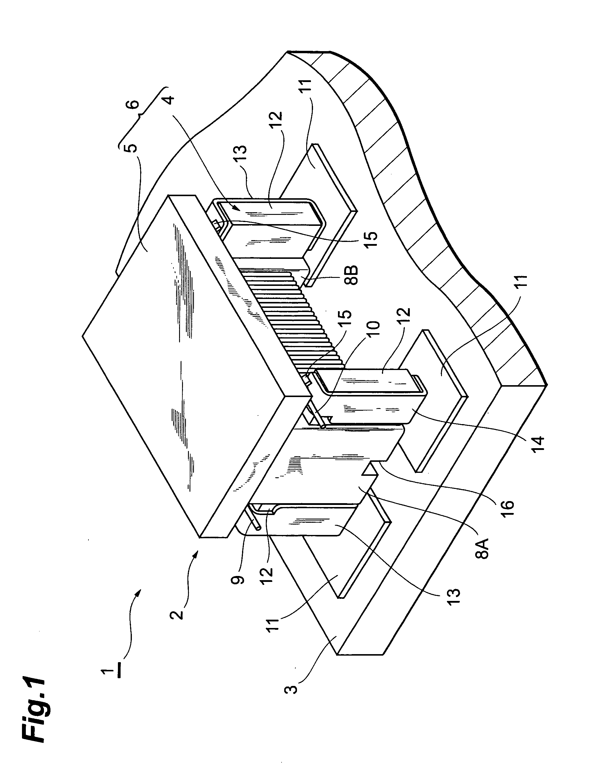
[0044] An electronic device 1 according to the first embodiment will be described first with reference to FIG. 1-FIG. 5. FIG. 1 is a perspective view depicting the electronic device according to the first embodiment. FIG. 2 is an exploded perspective view depicting the coil component shown in FIG. 1. FIG. 3 is a side view depicting the electronic device shown in FIG. 1. The electronic device 1 has a coil component 2. The coil component 2 is a common mode filter for a power supply line, for example. The coil component 2 is mounted on a circuit board 3 by conductive paste (Ag paste in this example) P. The coil component 2 comprises a core element 6 which has a drum core 4 and flat core 5. The core element 6 is made of a magnetic substance, such as ferrite, or a non-magnetic substance, such as ceramic. The coil component 2 is set, for example, to the length of about 4.5 mm, the width of about 3.2 mm, and the height of about 2.8 mm.

[0045] The drum core 4 has a core portion 7, and a pai...

second embodiment

[0063] Now, an electronic device 20 according to the second embodiment will be described with reference to FIG. 6-FIG. 11.

[0064]FIG. 6 is a perspective view depicting the electronic device 20 having a coil component according to the second embodiment. FIG. 7 is a perspective view depicting the coil component shown in FIG. 6. FIG. 8 is a side view depicting the electronic device shown in FIG. 6. The electronic device 20 has a coil component 21, instead of the coil component 2 in the first embodiment. The coil component 21 comprises a core element 24 which has a drum core 22 and a ring core 23. The core element 24 has a closed magnetic structure, so the leakage of magnetic flux can be decreased. The material of the core element 24 is the same as that of the core element 6 in the first embodiment.

[0065] As FIG. 9 and FIG. 10 show, the drum core 22 has a core portion 25 and a pair of flange portions 26A and 26B disposed on both ends of the core portion 25. The core portion 25 and the ...

third embodiment

[0074] Now, an electronic device 40 according to the third embodiment will be described with reference to FIG. 12-FIG. 14.

[0075]FIG. 12 is a perspective view depicting the electronic device according to the third embodiment. FIG. 13 is a cross-sectional view sectioned at XIII-XIII in FIG. 12. FIG. 14 is a bottom view depicting the coil component shown in FIG. 12. The electronic device 40 has a coil component 41, in stead of the coil component 2 in the first embodiment. The coil component 41 comprises a core element 42. The material of the core element 42 is the same as that of the core element 6 in the first embodiment.

[0076] The core element 42 has a core portion 43 and a top flange portion 44A and bottom flange portion 44B disposed on both ends of the core portion 43. The core portion 43 and the flange portions 44A and 44B are integrated. The shape of the core portion 43 and the flange portions 44A and 44B is a rectangular parallelepiped. The coils 9 and 10 are placed on the cor...


PUM

PropertyMeasurementUnit
temperatureaaaaaaaaaa
heightaaaaaaaaaa

Abstract

A coil component comprises a core element having a mounting portion, a coil conductor placed on the core element, and at least two terminal electrodes which are placed in the mounting portion. The mounting portion has at least two terminal placement areas for placing the terminal electrodes respectively. A hollow portion opening to the mounting side face of the mounting portion is formed in an area between the at least two terminal placement areas in the mounting portion. When mounting the coil component on a circuit board, conductive paste is intervened between an area from the terminal electrodes placed in the mounting portion of the core element to the base exposed area of the mounting portion, and the electrode patterns on the circuit board.

Description

BACKGROUND OF THE INVENTION [0001] 1. Field of the Invention [0002] The present invention relates to a coil component and an electronic device. [0003] 2. Description of the Related Art [0004] A known conventional coil component is a common mode choke coil disclosed in Japanese Patent Application Laid-Open No. 2003-77730, for example. The coil component disclosed in this document comprises a magnetic core having a core portion and a pair of flange portions disposed on both ends of the core portion, terminal electrodes, two of which are disposed on each flange of the magnetic core respectively, and two insulated coated conductors (coils) which are wound around the core portion of the magnetic core. In the electrode terminal portion, both ends of each insulated coated conductor are conductively connected respectively. SUMMARY OF THE INVENTION [0005] To mount this coil component on a circuit board, the terminal electrodes of the coil component are normally soldered to the electrode patt...

Claims


Application Information

Patent Timeline
Patent Type & Authority Applications(United States)
IPC IPC(8): H01F27/28
CPCH01F17/045H01F27/027H01F27/292H05K2201/10628H01F2017/0093H05K3/321H01F27/38
Inventor YASUDA, MASATOSHIKUDO, SHINSUZUKI, HIROSHIKOBAYASHI, KATSUMI
Owner TDK CORPARATION
Why Eureka
Try Eureka