Method and system for digital spur cancellation

a technology of digital spur and cancellation method, applied in the field of bluetooth and fm communication technologies, can solve the problems of affecting the coexistence of handheld devices such as cellphones that incorporate bluetooth and wireless lan, and requiring significant processing overhead

Active Publication Date: 2006-11-30
NXP USA INC
View PDF5 Cites 80 Cited by
  • Summary
  • Abstract
  • Description
  • Claims
  • Application Information

AI Technical Summary

Benefits of technology

[0010] A system and/or method is provided for digital spur cancellation, substantially as shown in and/

Problems solved by technology

However, integrating multiple audio communication technologies into a single device may be costly.
Moreover, coordinating the reception and/or transmission of data to and/or from the portable electronic device or a wireless device may require significant processing overhead that may impose certain operation restrictions and/or design ch

Method used


Image

  • Method and system for digital spur cancellation
  • Method and system for digital spur cancellation
  • Method and system for digital spur cancellation

Examples


Embodiment Construction

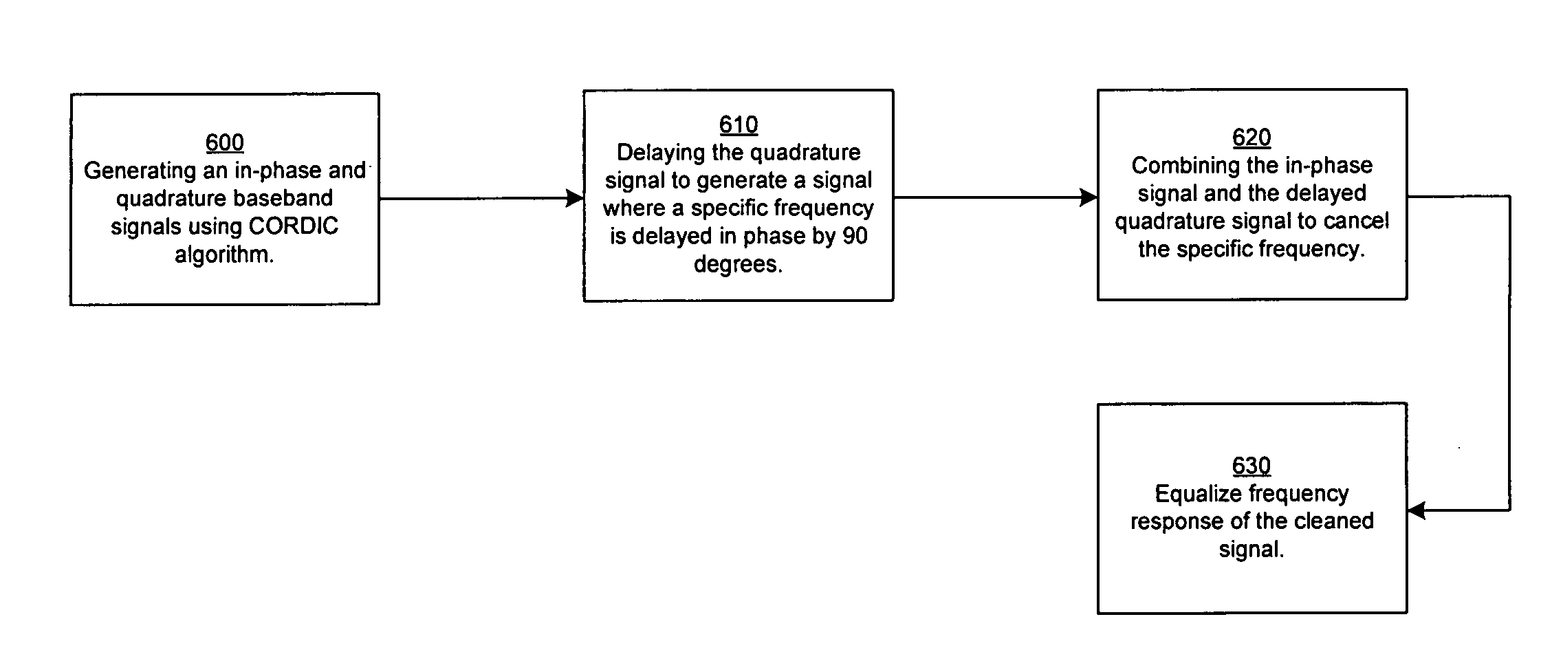
[0037] Certain embodiments of the invention may be found in a method and system for digital spur cancellation. Aspects of the method may comprise removing a spur in a first left channel minus right channel (L−R) baseband signal generated from a FM signal. The first L−R baseband signal may be generated by demodulating a sub-carrier in a signal demodulated from the FM signal. A CORDIC algorithm, for example, may be used to demodulate the sub-carrier. The CORDIC algorithm may also generate an orthogonal signal where the phase of the orthogonal signal may be substantially −90° out of phase with respect to an in-phase signal. The phase of the orthogonal signal may be further adjusted to introduce a substantially −90° phase shift to the spur, which may be at a specific frequency. A shift register that may utilize a clock at an appropriate frequency may introduce the phase shift to the spur. Alternatively, Hilbert transform may be used to phase shift the spur. Accordingly, the spur in the ...


PUM


Abstract

A method and system for digital spur cancellation may include removing a spur in a left channel minus right channel (L−R) baseband signal generated from a FM signal. The L−R baseband signal may be generated by demodulating a sub-carrier, for example, by using CORDIC algorithm, in a signal demodulated from the FM signal. An orthogonal signal may also be generated by demodulating a sub-carrier, for example, by using CORDIC algorithm, in a signal demodulated from the FM signal. The phase of the orthogonal signal may be further adjusted to introduce a substantially −90° phase shift to spurs at a specific frequency. Accordingly, the spurs in the L−R baseband signal may be cancelled when the first L−R baseband signal is combined with the phase adjusted orthogonal signal.

Description

CROSS-REFERENCE TO RELATED APPLICATIONS / INCORPORATION BY REFERENCE [0001] The application makes reference to, claims priority to, and claims the benefit of U.S. Provisional Application Ser. No. 60 / 685,239 filed on May 26, 2005. [0002] This application also makes reference to: U.S. application Ser. No. ______ (Attorney Docket No. 16663US02) filed on even date herewith; U.S. application Ser. No. ______ (Attorney Docket No. 17106US02) filed on even date herewith; U.S. application Ser. No. ______ (Attorney Docket No. 17107US02) filed on even date herewith; U.S. application Ser. No. ______ (Attorney Docket No. 17108US02) filed on even date herewith; U.S. application Ser. No. ______ (Attorney Docket No. 17109US02) filed on even date herewith; U.S. application Ser. No. ______ (Attorney Docket No. 17113US02) filed on even date herewith; U.S. application Ser. No. ______ (Attorney Docket No. 17115US02) filed on even date herewith; U.S. application Ser. No. ______ (Attorney Docket No. ...

Claims


Application Information

Patent Timeline
IPC IPC(8): H04K1/10
CPCH04L25/03159H04W28/04H04L27/34H04L27/14Y02D30/70
Inventor IBRAHIM, BRIMAKIM, HEA JOUNGMARHOLEY, BOJKO
Owner NXP USA INC
Why Eureka
Try Eureka