
Integrated microfluidic sperm isolation and insemination device

Inactive Publication Date: 2006-11-30
THE RGT OF THE UNIV OF MICHIGAN
View PDF13 Cites 45 Cited by
  • Summary
  • Abstract
  • Description
  • Claims
  • Application Information

AI Technical Summary

Benefits of technology

[0008] An integral device which both sorts sperm based on motility and then uses the sorted sperm to inseminate an oocyte, consists of minimally two gravity driven pumps, one for semen and one for a media fluid, and a common sort channel wherein more motile sperm swi

Problems solved by technology

Use of the sperm to fertilize an oocyte also generally involves numerous manipulative steps which can cause damage to the fragile oocytes.
Since these procedures involve complex, microscopic manipulative steps, as described earlier, they are, in general, quite expensive.

Method used


Image

  • Integrated microfluidic sperm isolation and insemination device
  • Integrated microfluidic sperm isolation and insemination device
  • Integrated microfluidic sperm isolation and insemination device

Examples


example 1

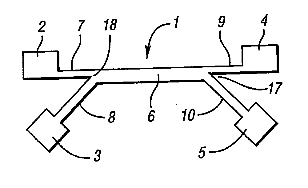
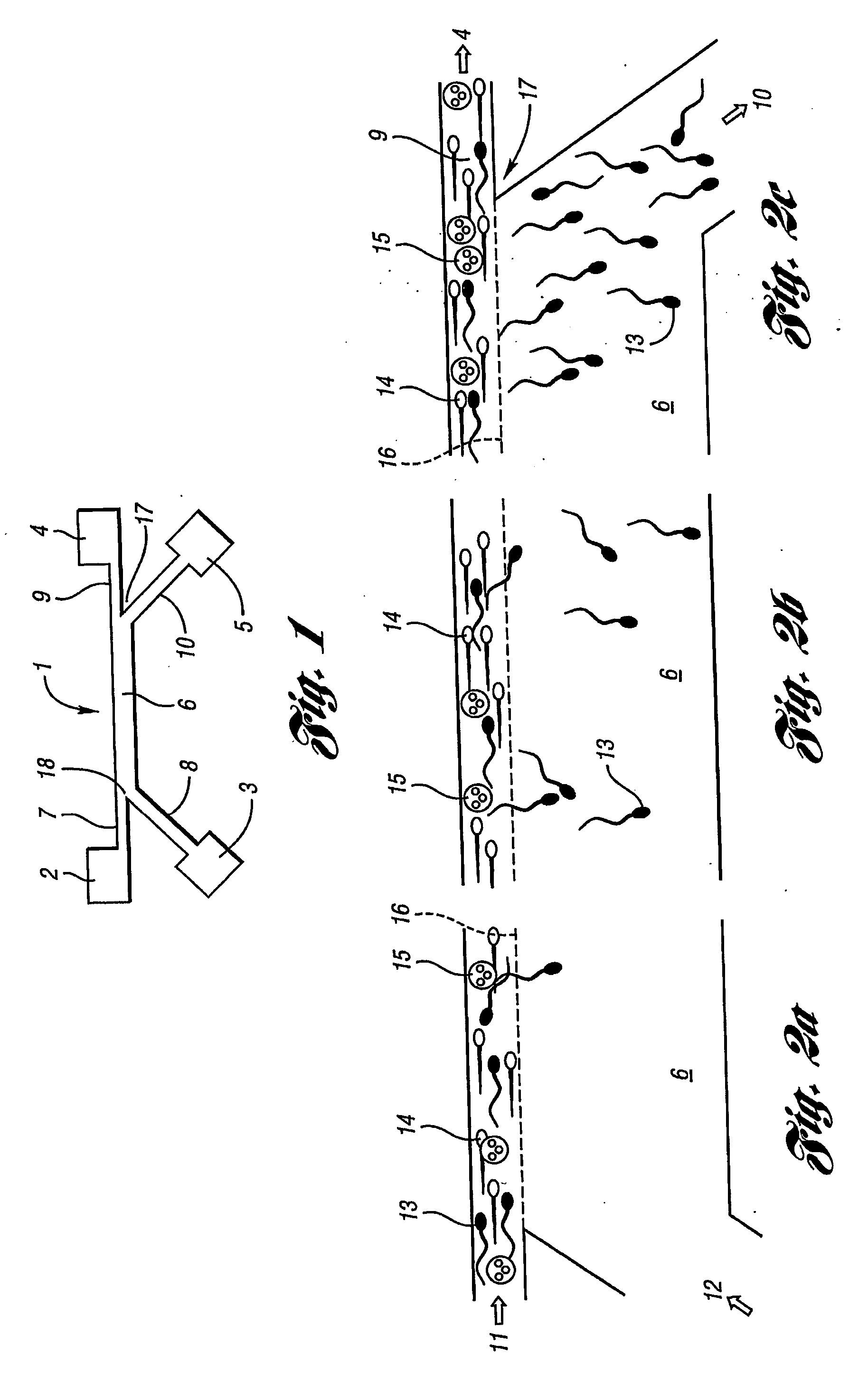
[0070] A microfluidic sperm sorting device is prepared from Dow Corning SYLGARD® 184 curable silicone resin, using the soft lithography technique described by D. C. Duffy et al., cited previously. The curable PDMS is cast onto a master having the desired reservoir and channel features as protuberances. The cast PDMS sorting devices are plasma oxidized to seal the open channel side of the casting to a glass cover slide. Channels and reservoirs are coated with 1% bovine serum albumin fraction V from Sigma, dissolved in phosphate buffered saline (PBS) from Invitrogen Corporation. The entire device is approximately 6 mm thick, exclusive of the cover slide, and somewhat larger than a U.S. penny coin. A perspective view of the device is shown in FIG. 1.

[0071] In FIG. 1, the PDMS casting is transparent, and only the reservoirs and channels are depicted. A glass cover slide or other substrate would be bonded to the bottom plane of the device. The channels are rectangular in cross-section, ...

example 2

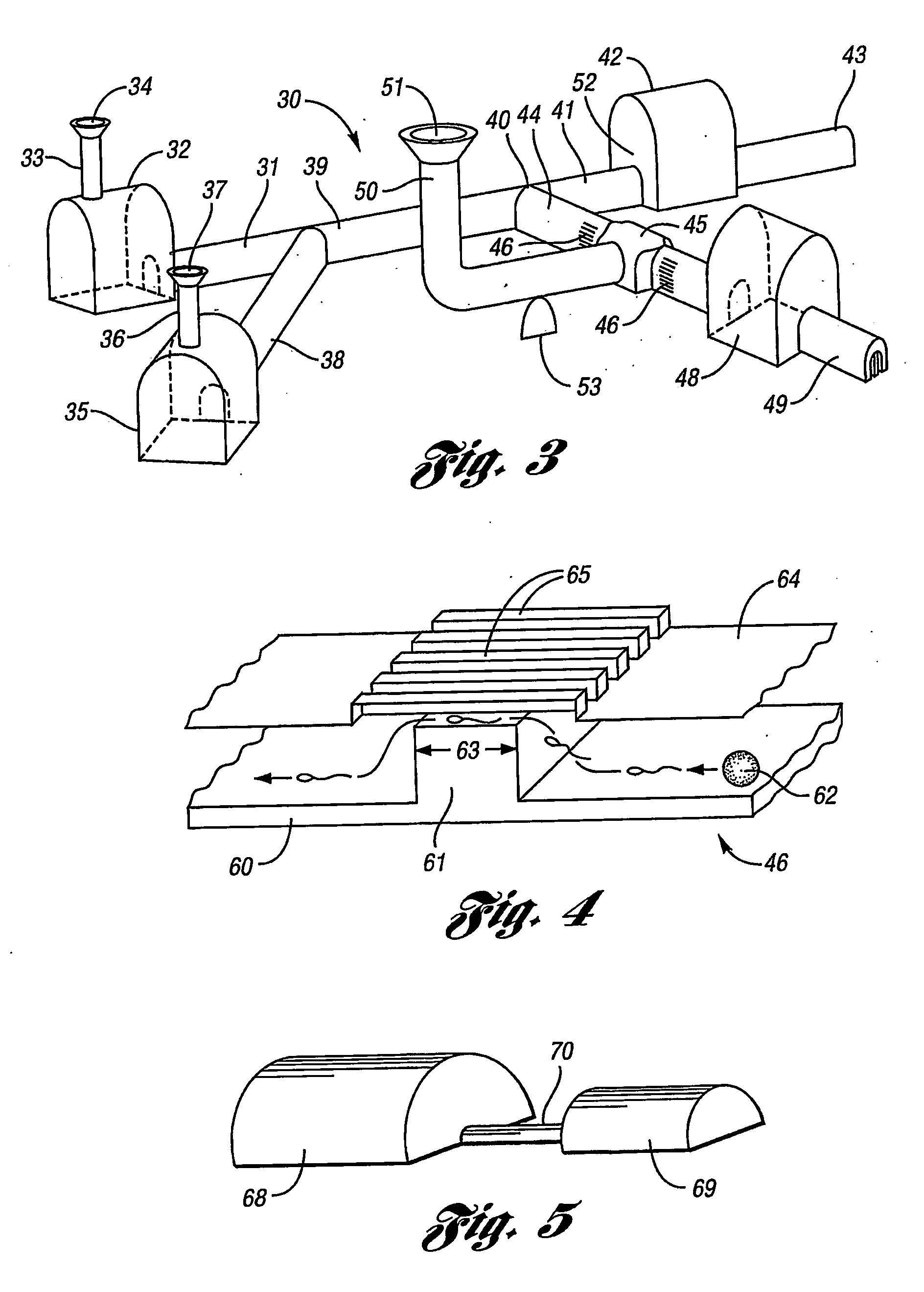
[0077] A device similar to that of Example 1 is configured with a funnel shaped oocyte duct communicating with the channel leading to the sorted sperm reservoir, as shown in FIG. 3. Prior to the beginning of sperm sorting, a mouse cumulus mass (20-30 oocytes) is introduced by means of a pipet. Mouse sperm is introduced into the sperm reservoir and media fluid into the media fluid (sort fluid) reservoir. One co-laminar flow begins, more motile sperm cross over the interface between the co-flowing streams, and the sperm-enriched media fluid flows into the sorted sperm reservoir collection well (volume: ca. 30-40 μL), which also serves as the insemination chamber. Successful fertilization is noted following 24 hours of co-incubation within the collection well (insemination chamber).

example 3

[0078] A microfluidic channel / insemination device is fabricated from PDMS by the layering technique. A single microchannel connects two larger reservoirs, one having a fuel shaped oocyte duct attached thereto, which also serves as a fluid inlet. The microchannel is 500 μm wide by 180 μm deep, and is about 2 cm long. After about 80% of its length, the channel contains a barrier grate as depicted by FIG. 4. The parallel channels of the barrier grate are prepared as a separate PDMS layer and subsequently bonded to the layer containing the channel.


PUM


Abstract

An integrated microfluidic sperm isolation and oocyte insemination device provides the opportunity to perform in vitro insemination with motilityenhanced sperm samples and with minimal manipulation of fragile oocytes. Sperm sorting is performed in a common sort channel wherein more mobile sperm swim across the interface between co-laminar flows of semen and media fluid.

Description

CROSS-REFERENCE TO RELATED APPLICATIONS [0001] This application claims the benefit of U.S. provisional application Ser. No. 60 / 476,664 filed Jun. 6, 2003.BACKGROUND OF THE INVENTION [0002] 1. Field of the Invention [0003] The present invention is directed to an integral microfluidics device which sorts sperm based on sperm motility and utilizes sorted sperm for oocyte insemination, to a method for its use, and to a further method for microfluidic insemination of oocytes. [0004] 2. Background Art [0005] Conventional in vitro insemination techniques involve separation of more motile sperm from non-motile sperm, deformed sperm, cellular debris, etc.; by techniques which can damage the sperm. Even so, hand sorting is frequently necessary. Use of the sperm to fertilize an oocyte also generally involves numerous manipulative steps which can cause damage to the fragile oocytes. For example, intracytoplasmic sperm injection has been used, particularly when the availability of viable sperm i...

Claims


Application Information

Patent Timeline
IPC IPC(8): C12M1/00
CPCB01L3/50273B01L3/502753B01L2400/0487B01L2200/0636B01L3/502776
Inventor TAKAYAMA, SHUICHISMITH, GARY D.SUH, RONALD
Owner THE RGT OF THE UNIV OF MICHIGAN
Learn More