
Method and device for power amplifier with high accuracy of an ouput signal

a technology of output signal and power amplifier, which is applied in the direction of amplifier modification, transmission monitoring, modulation, etc., can solve the problems of limited power amplifier efficiency, inconvenient operation, and high cost of power amplifiers in communication systems, so as to improve the output signal accuracy of power amplifiers in transmitters

Inactive Publication Date: 2006-11-30
TELEFON AB LM ERICSSON (PUBL)
View PDF4 Cites 12 Cited by
  • Summary
  • Abstract
  • Description
  • Claims
  • Application Information

AI Technical Summary

Benefits of technology

[0009] It is therefore an object of the present invention to overcome the above-mentioned problems and to provide a method for improving output signal accuracy of power amplifiers in a transmitter.
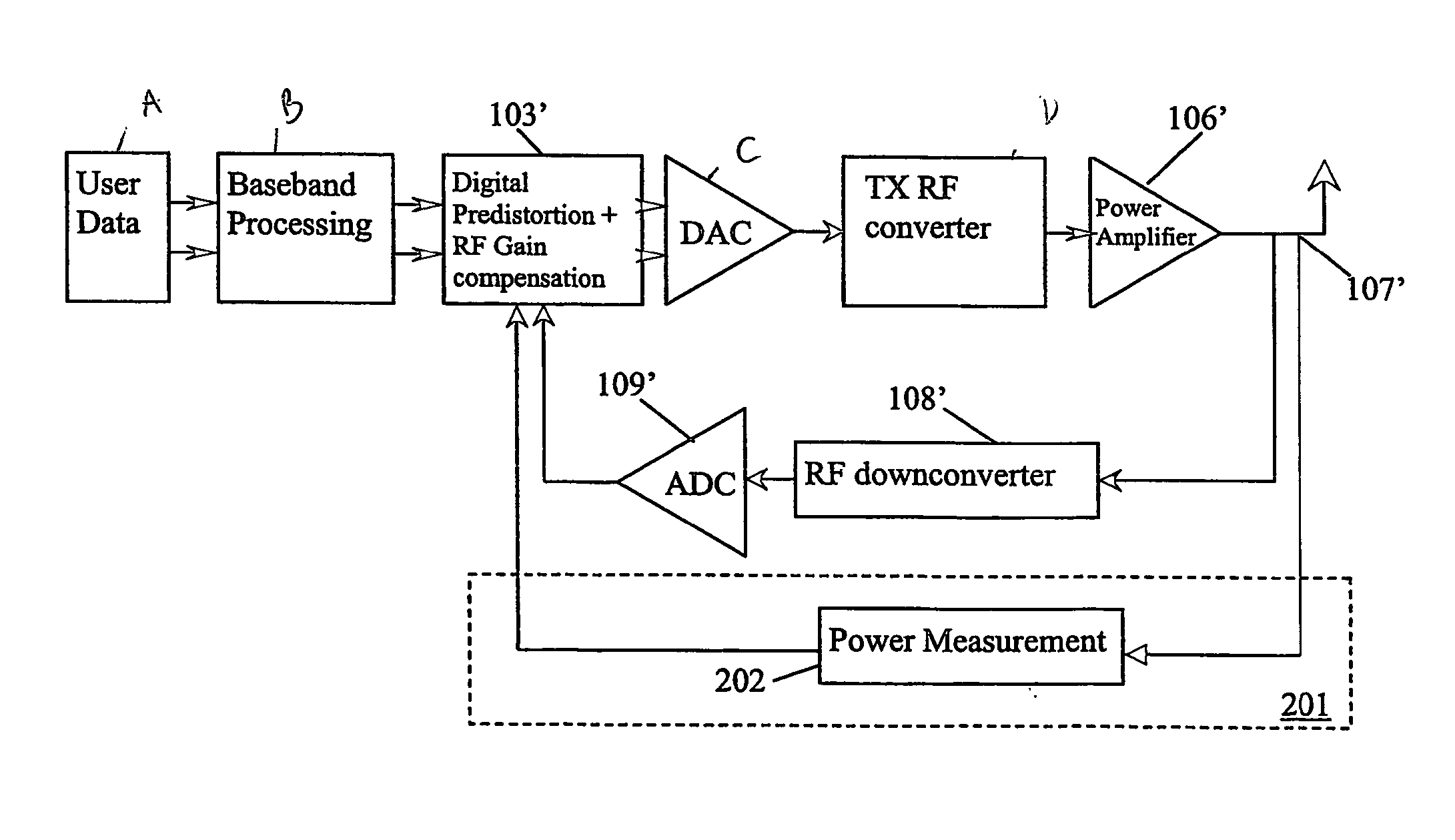
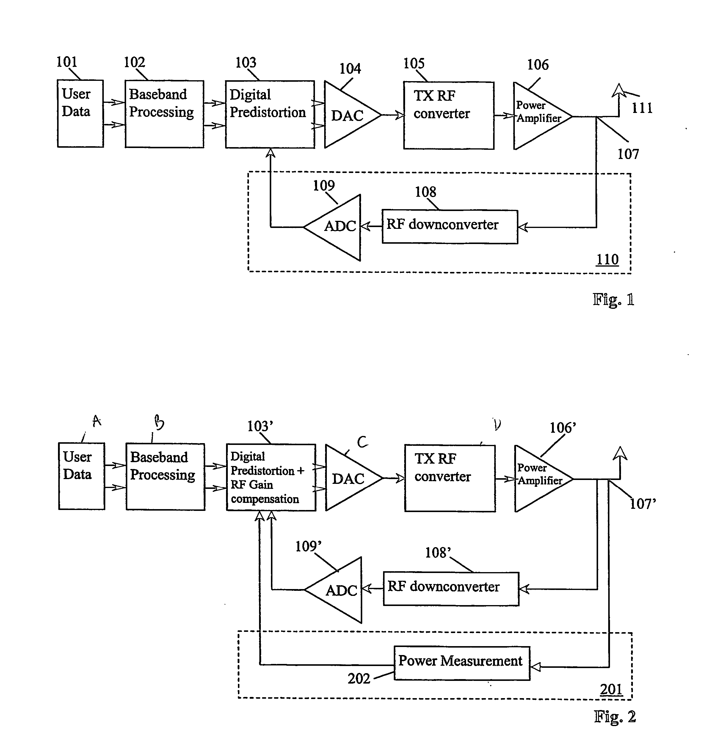
[0012] The feedback signal is fed back to the adaptation unit and the predistortion applied to the input signal is determined according to the feedback signal. According to the invention the output power of said signal for transmission is measured in a second feedback branch and the predistortion is adjusted according to said measurement of the output power. It should be noted that the adjustment can either be performed on the feedback signal before it is forwarded to the adaptation unit or the adjustment may be performed by the adaptation unit itself. Preferably, however, adjusting according to said measurement is performed on the feedback signal, either within or before the adaptation unit. A major advantage of using a second feedback branch is that the power measurement can be performed without prior processing stages for signal conversion, which significantly improves the measurement precision. It is furthermore possible to correct inaccuracies in the amplification of the first feedback branch allowing for a cheap implementation.
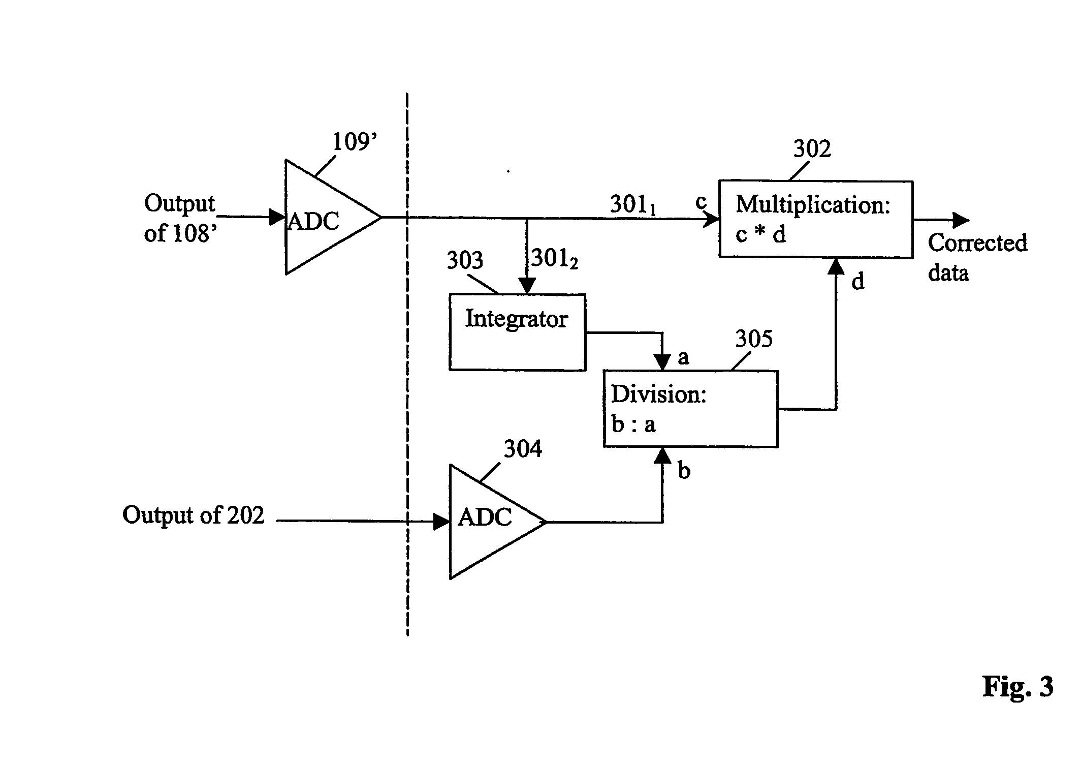
[0016] The output power measurement values may be subject to further processing for calculating gain compensation. Especially, the gain compensation may be calculated by a method which further comprises the steps of comparing the analog-to-digital converted values of the first feedback branch with the analog-to-digital converted output power measurement values of the second feedback branch, deriving a correction factor from said comparison and multiplying said analog-to-digital converted values of the first feedback branch with said correction factor. In this way, a simple compensation of gain variations may be achieved.
[0017] In order to provide corrections for gain uncertainties of the first feedback branch to the digital adaptation unit, the RF downconverted signals may be integrated such as the output power measurement signals. If gain correction data shall be calculated after an analog-to-digital conversion it is advantageous to make use of the same time constant for integrating the RF-downconverted signals and for the output power measurement. This allows a frequent comparison of the RF-downconverted signals of the first feedback branch and the power measurements of the second feedback branch and can be easily implemented. Therefore in a preferred embodiment of the method the time constant used for integrating the output power measurement of the second feedback branch and for integrating said analog-to-digital-converted values of the first feedback branch are the same.
[0023] In an advantageous transmitter, the measurement unit is an integrating measurement unit, allowing for a low implementation effort and low costs. Preferably, the measurement unit is working at radio frequency in the analog domain.

Problems solved by technology

The drawback associated with a large peak-to-average power ratio is that it limits the power amplifier efficiency.
If power amplifiers are run close to saturation high peak values lead to significant intermodulation distortion, such that adjacent channels experience significant interference.
This approach, however, has the disadvantage that power amplifiers are an expensive part of a communication system.
Power amplifiers with high back-off result in significant extra cost for the system.
In addition power amplifiers with high back-off cause size as well as heat dissipation problems.
The major drawback of this solution results from the fact that predistortion is performed according to the feedback signal, generally in the digital domain.
This analog equipment in communication system components such as radio base stations or mobile terminals is subject to high variations associated with environmental temperature and also aging and power supply variations.
These gain uncertainties in the down-conversion feeback branch cause output power variations of the same magnitude.
This approach, however, suffers from the disadvantage that the down-conversion components become very expensive, need a relevant amount of space in a hardware implementation and finally result in additional heat dissipation.

Method used


Image

  • Method and device for power amplifier with high accuracy of an ouput signal
  • Method and device for power amplifier with high accuracy of an ouput signal
  • Method and device for power amplifier with high accuracy of an ouput signal

Examples


Embodiment Construction

[0031] In the following description, for purposes of explanation and not limitation, specific details are set forth, such as particular embodiments, circuits, signal formats etc. in order to provide a thorough understanding of the present invention. It will be apparent to one skilled in the art that the present invention may be practiced in other embodiments that depart from these specific details. In particular, while the different embodiments are described herein below incorporated with a Wideband CDMA transmission device, the present invention is not limited to such an implementation, but for example can be utilized in any transmission device in which a signal adaptation can be performed in the forward branch, e.g. an analog or digital predistortion. Moreover, those skilled in the art will appreciate that the functions explained herein below may be implemented using individual hardware circuitry, using software functioning in conjunction with a programmed microprocessor or genera...


PUM


Abstract

The invention relates to a method for improving the output signal accuracy of a transmitter with a forward branch for converting an input signal into a signal for transmission. The forward branch comprises an adaptation unit (103) for applying a predistortion to the input signal and a power amplifier (106). The transmitter has a first feedback branch (110), the first feedback branch (110) generating a feedback signal from the signal for transmission, said feedback signal being fed back to the adaptation unit (103), and the predistortion applied to the input signal is determined according to the feedback signal. The method comprises the steps of: measuring the output power of said signal for transmission in a second feedback branch (201) and adjusting the predistortion according to said measurement of the output power. A transmitter and a computer program product adapted to the method are also described.

Description

FIELD OF THE INVENTION [0001] The present invention relates to a method and a device for improving the output signal accuracy of a power amplifier in a transmitter. More specifically, the invention relates to a method and a device for improving the output signal accuracy of power amplifiers in conjunction with digital predistortion. BACKGROUND OF THE INVENTION [0002] Efficient multiple access techniques are an important prerequisite to guarantee the high traffic handling capacities of modem telecommunication systems. Multiple access techniques permit a plurality of users to simultaneously access a specific resource by dividing a common communications medium into individual channels. [0003] There are three basic types of multiple access techniques, namely frequency division multiple access (FDMA), time division multiple access (TDMA) and code division multiple access (CDMA). Unlike FDMA and TDMA, CDMA allows a plurality of different traffic channel signals to be simultaneously transm...

Claims


Application Information

Patent Timeline
Patent Type & Authority Applications(United States)
IPC IPC(8): H04B1/04H04B17/00H01Q11/12H03F1/32
CPCH03F1/3252H03F1/3247
Inventor KEHLENBACH, WERNER
Owner TELEFON AB LM ERICSSON (PUBL)
Learn More