
Dialysis catheter

a dialysis catheter and catheter technology, applied in the field of catheters, can solve the problems of increasing the overall cost of the catheter system, time-consuming and labor-intensive surgical procedures, and complicating the surgical procedure, so as to facilitate the insertion and increase the stiffness of the catheter

Inactive Publication Date: 2006-11-30
ARGON MEDICAL DEVICES
View PDF99 Cites 32 Cited by
  • Summary
  • Abstract
  • Description
  • Claims
  • Application Information

AI Technical Summary

Benefits of technology

[0033] In a preferred embodiment, the distal portion of the catheter includes a stiffening insert embedded in a wall of the catheter at the distal portion and a stiffening member is removably positionable within the catheter body in engagement with the region of the catheter wall adjacent the stiffening insert to temporarily increase the stiffness of the catheter to facilitate insertion.
[0036] The distal tip portion preferably includes multiple tapered regions of differing degrees. The catheter may further comprise a stiffening member removably positionable within the catheter to temporarily increase the stiffness of the catheter to facilitate insertion.

Problems solved by technology

This multiple step process of inserting the Medcomp dialysis catheter is time consuming and complicates the surgical procedure.
These multiple steps add to the cost of the procedure, not only because of the additional surgeon's time but because additional components, such as the tear-away sheath, are required which increases the overall cost of the catheter system.
Also, removal of the dilator increases the tendency of the sheath to kink causing difficulties in catheter insertion.
The use of the tear away sheath is also potentially problematic.
However, the sheath can potentially cause damage to the vessel wall as it is being pulled apart and can cause infection.
Moreover, pulling the sheath laterally can enlarge the incision, thereby increasing the difficulty of closing the incision at the end of the procedure.
The edges of the tear away can also lacerate the surgeon's glove and finger.
Over dilation by the sheath can cause blood leakage.
An additional potential risk with utilizing tear away sheaths is that air embolism can occur.
If the patient inhales during this catheter exchange, an air bubble can enter the vascular system and obstruct the vessel, potentially causing stroke or even death.
This flexibility, however, oftentimes results in kinking of the catheter since the catheter must navigate curves to reach the target vessel.
This kinking can adversely affect blood flow.
The stiffness, however provides its own risks since if the catheter is not properly directed, the catheter can inadvertently be forced against the vessel wall, thereby puncturing or damaging the vessel.
If the lumens are too small, sufficient blood flow may not be able to be maintained and the blood can be damaged during transport.
However, a problem with prior dialysis catheters is that during blood withdrawal, as suction is being applied through the catheter openings and lumen, the suction can cause the catheter to be forced against the side wall of the vessel, known as “side port occlusion”, which can block the opening and adversely affect the function of the catheter by enabling only intermittent suction.
This fibrin growth, caused by the body's attempt to reject the catheter as a foreign body, could result in blocking of the suction holes.

Method used


Image

  • Dialysis catheter
  • Dialysis catheter
  • Dialysis catheter

Examples


first embodiment

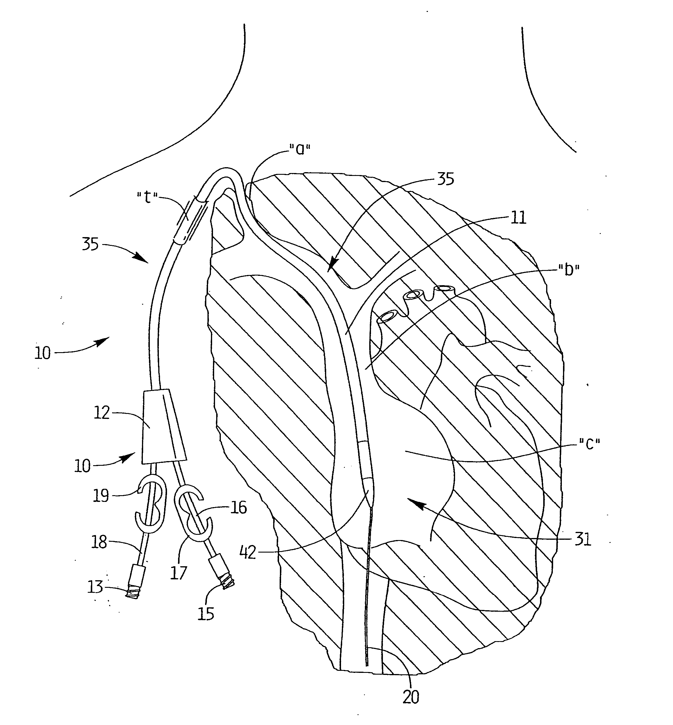
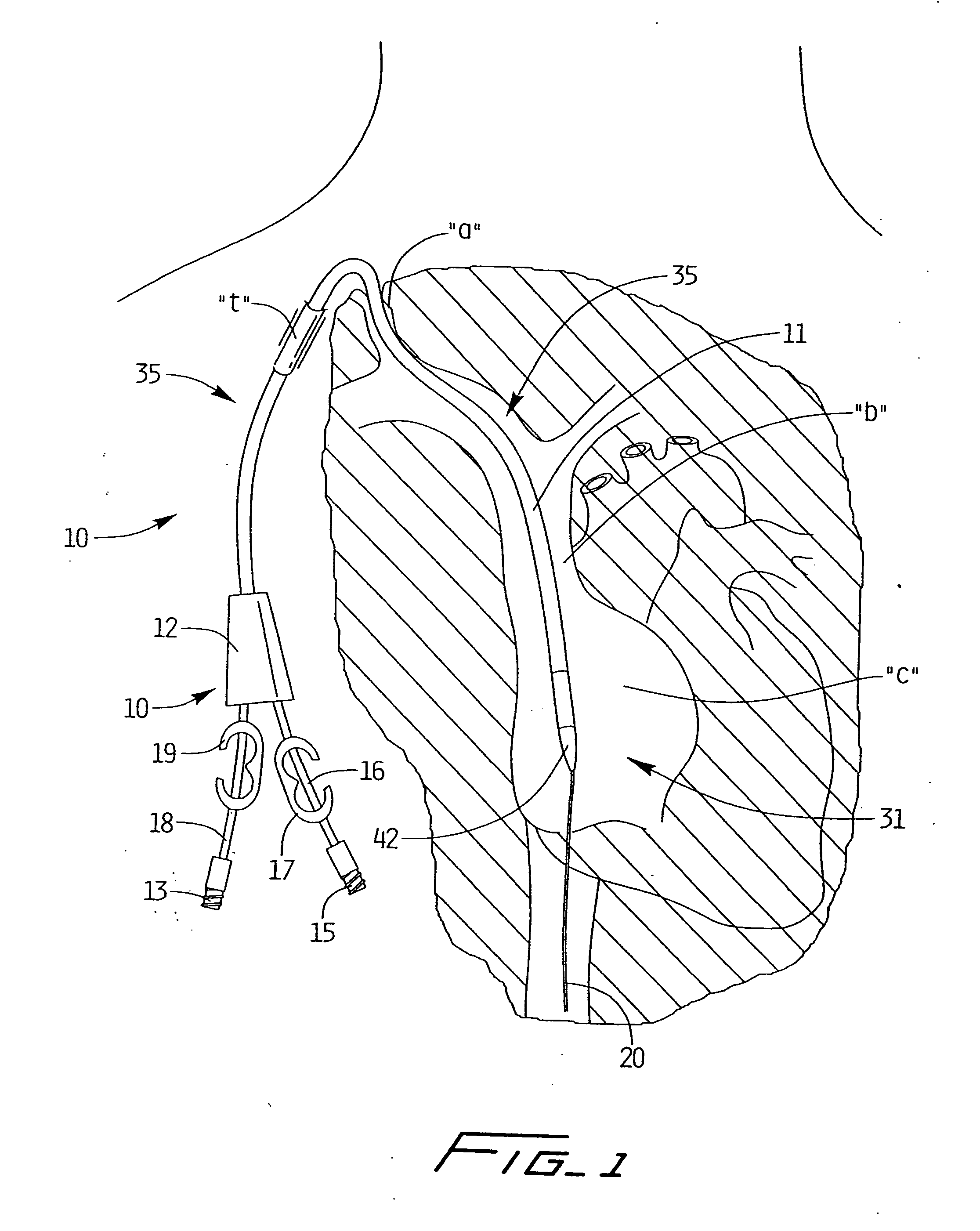
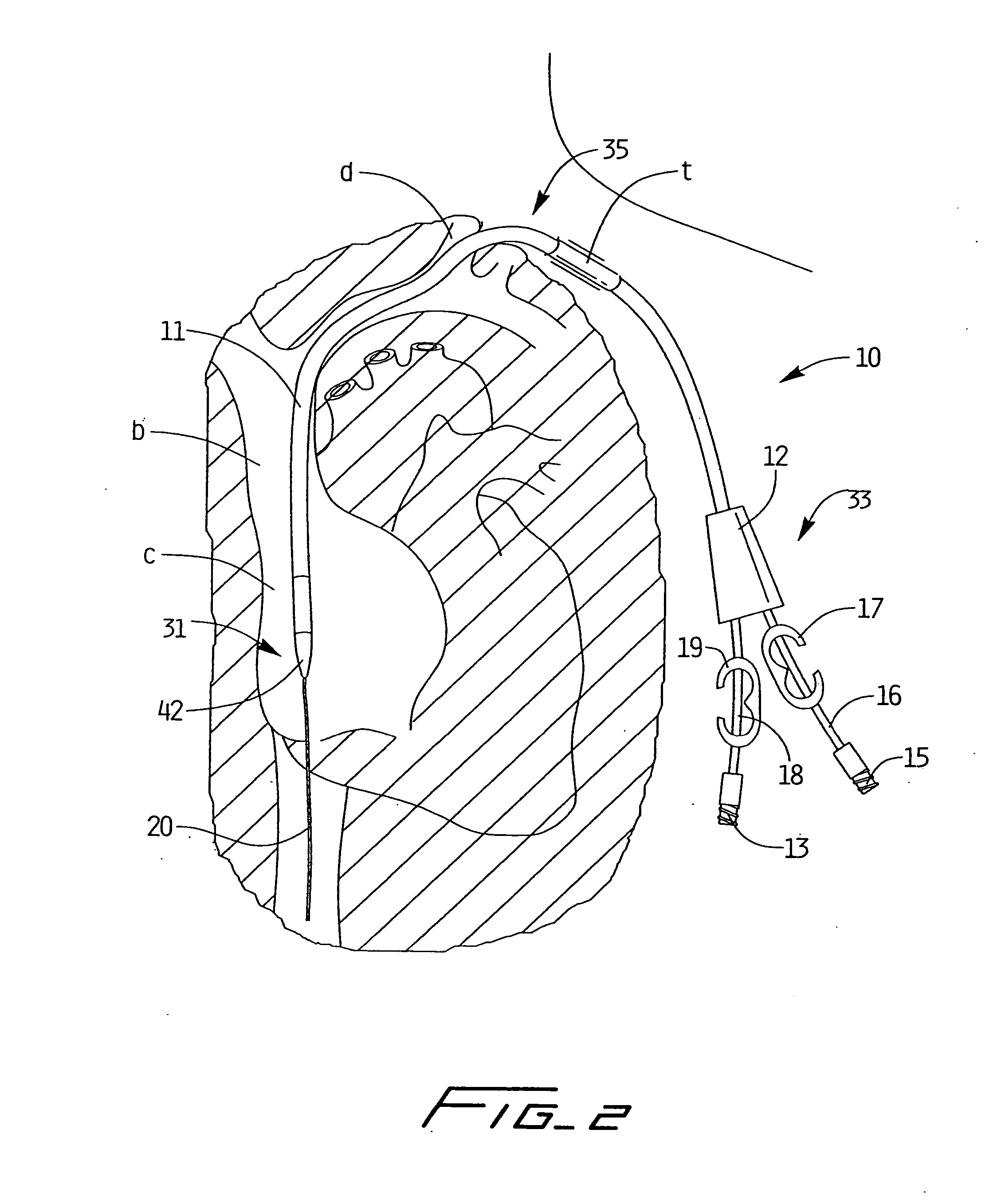
[0127] Referring now in detail to the drawings where like reference numerals identify similar or like components throughout the several views, the catheter of the present invention is designated generally by reference numeral 10. The catheter 10 is typically inserted into an area of high velocity blood flow to ensure sufficient blood can be transported from the body for dialysis. FIG. 1 illustrates the catheter 10 inserted through the right internal jugular vein “a”, into the superior vena cava “b”, and into the right atrium “c”; FIG. 2 illustrates the catheter 10 inserted into the left internal jugular vein “d”, into the superior vena cava “b” and into the right atrium “c”. Insertion into the right atrium, from either the right or left side provides the necessary high blood flow to the dialysis machine. Note that the catheter body (catheter tube) 11 is sufficiently flexible to enable it to bend to accommodate the anatomical curves as shown.

[0128] Catheter 10 has a catheter body or ...

third embodiment

[0142] To facilitate insertion, the catheter is configured to receive a stiffening member in the form of a stiffening rod which stretches the catheter to reduce its profile to aid in over the wire insertion and better navigate through small vessels. That is, the stiffening rod is inserted into central lumen 40 of catheter 10 and torqued to stiffen the flexible catheter for ease in over the wire insertion and navigation through the small vessels, and to reduce the outer diameter of the catheter body by stretching it during insertion. After placement of the catheter 10, the stiffening rod is removed, allowing the catheter to return to its higher profile position with the lumens of the necessary size for blood transport to and from the body. Two embodiments of the stiffening rods are illustrated in FIGS. 4A and 4B and are shown prior to insertion into the catheter 10 in FIG. 3. the stiffening rod is illustrated in FIG. 49.

[0143] Turning to the fast embodiment of the stiffening rod illu...


PUM


Abstract

A dialysis catheter comprising a first portion having a first dianeter, an elongated distal portion having a second diameter smaller than the first diameter, and a transition region between the first portion and distal portion. A first longitudinally extending central lumen configured to deliver blood terminates in an opening in the distal portion. At least two independent longitudinally extending lumens are positioned radially of the first lumen, configured to withdraw blood from a patient, and terminate in a longitudinally directed opening in the transition portion.

Description

BACKGROUND [0001] This application is a continuation-in part of application Ser. No. 10 / 025,506, filed Dec. 19, 2001, which claims priority from provisional patent application Ser. No. 60 / 260,592, filed Jan. 9, 2001. The entire contents of these applications are incorporated herein by reference. TECHNICAL FIELD [0002] This application relates to a catheter and more particularly to a multi-lumen catheter which facilitates hemodialysis. BACKGROUND ART [0003] Hemodialysis is a well known method of providing renal (kidney) function by circulating blood. The kidneys are organs which function to extract water and urea, mineral salts, toxins, and other waste products from the blood with filtering units called nephrons. From the nephrons the collected waste is sent to the bladder for excretion. For patients having one or both defective kidneys, the hemodialysis procedure is life saving because it provides a machine to simulate the function of the kidneys. [0004] In the hemodialysis procedur...

Claims


Application Information

Patent Timeline
Patent Type & Authority Applications(United States)
IPC IPC(8): A61M37/00A61M5/178A61B17/34A61M39/10A61M1/28A61M25/04
CPCA61M1/285A61M25/0028A61M25/0029A61M25/0032A61M25/0082A61M2025/0078A61M25/04A61M25/09041A61M2025/0031A61M2025/0034A61M2025/0036A61M25/0097A61M1/3661
Inventor MCGUCKIN, JAMES F. JR.PARIS, MICHAEL W.TASHJIAN, PAULHINCHLIFFE, PETER W.J.
Owner ARGON MEDICAL DEVICES
Learn More